Wind is naturally an action variable in time on a structure located outdoors. The wind load is classified as a variable, free action so that the loading can be combined with other actions (for example, imposed load or snow) in defined design situations according to the combination standard DIN EN 1990. Changes in the aerodynamic coefficients due to other actions (snow, traffic, or ice) and due to modifications of the structure have to be considered during construction. However, windows and doors are assumed as closed in case of wind loads. Windows and doors that are unavoidably open have to be considered as accidental design situations.
The dynamic wind load has to be displayed in a simplified way as equivalent wind pressure or wind force to the maximum action of turbulent wind. Wind acts on the outer surfaces in case of closed structures and additionally on the inner surfaces in case of permeable or open structures. The action has to be applied as perpendicular to the surfaces considered. In case of large surfaces under circulating wind, a friction component has to be considered additionally, parallel to the surface area.
The wind standard DIN EN 1991-1-4 with the National Annex of Germany specifies the wind load as a characteristic value. This value is determined by a basic wind velocity with an annual probability exceedance value of 2% and an average return period of 50 years.
The resulting wind load in case of sufficiently rigid buildings not susceptible to vibrations can be described as a static equivalent force that depends on the peak velocity. In contrast, for buildings susceptible to vibrations, the peak velocity is additionally modified with a structural factor to determine the static equivalent load [1], [2].
In simple terms, structures are not considered as susceptible to vibrations if the deformation under wind load caused by gusty wind resonance is not increased by more than 10%. This criterion applies to typical buildings with a height of up to 25 m that are not susceptible to vibrations. In all other cases, the following classification criterion can be used [3]:
where
xS = is the head displacement in m due to self-weight applied in the wind direction
h = building height in m; href = 25 m
b = width of the building perpendicular to the wind direction in m
δ = logarithmic decrement of damping according to DIN EN 1991-1-4, Annex F
| Type of Structure | Building Damping δmin |
|---|---|
| Reinforced concrete structure | 0.1 |
| Steel structure | 0.05 |
| Mixed structure (steel and concrete) | 0.08 |
Height-Dependent Peak Velocity Pressure
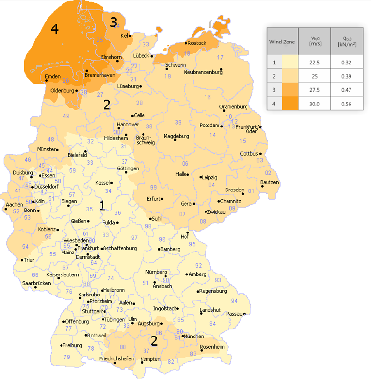
The wind load on a building not susceptible to vibrations depends on the peak velocity pressure qp. This value results from the wind velocity of a gust of wind with a length of two to four seconds by taking into account the surrounding terrain conditions. To determine the load at a location, the National Annex of Germany contains a wind zone map with corresponding basic values of the basic wind velocities vb,0, the basic values of the basic wind velocity pressures qb,0, and a specification of various terrain types (categories I - IV) [1], [2], [3].
If the wind zone increases, the basic value of the basic wind velocity increases as well.
The terrain category increases with the roughness of the terrain.
| Terrain | Description |
|---|---|
| Terrain category I | Open sea; lakes with at least 5 km open area in the wind direction; smooth, flat land with no obstacles |
| Terrain category II | Site with hedges, individual farms, houses, or trees (for example, agricultural area) |
| Terrain category III | Suburbs, industrial or commercial areas; forests |
| Terrain category IV | Urban areas where at least 15% of the area is covered with buildings of which the average height exceeds 15 m |
| Mixed profile coast | Transition region between terrain categories I and II |
| Mixed profile inland | Transition region between terrain categories II and III |
The peak velocity pressure vb,0 can be determined by defining the basic value of the basic wind velocity qp and the terrain type.
| Peak Velocity Pressure qp in kN/m² [3] | Approach 1 Table NA-B.1 | Approach 2 NA.B.3.3 | Approach 3 NA.B.3.2 | |||||||
|---|---|---|---|---|---|---|---|---|---|---|
| Influence of Sea Level NNmod | Less than 800 m above sea level | 1.0 | ||||||||
| Between 800 m and 1,100 m above sea level | 0.2 + Hs/1,000 | |||||||||
| More than 1,100 m above sea level | Special considerations required | |||||||||
| Wind Zone | 1 | 2 | 3 | 4 | 1 | 2 | 3 | 4 | ||
| Fundamental Basic Wind Velocity vb,0 in m/s | 22.5 | 25.0 | 27.5 | 30.0 | - | - | - | - | ||
| Directional Factor cdir | 1.0 | - | - | - | - | |||||
| Seasonal Factor cseason | 1.0 | - | - | - | - | |||||
| Basic Velocity Pressure qb in kN/m² | 0.32 | 0.39 | 0.47 | 0.56 | - | - | - | - | ||
| Terrain Category | Building Height | qp in kN/m² | ||||||||
| qp(z) in kN/m² | ||||||||||
| Terrain Category I | Up to 2 m | 1.90 ⋅ qb ⋅ NNmod- | - | - | - | - | ||||
| 2 m to 300 m | 2.60 ⋅ qb ⋅ (z/10)0.19 ⋅ NNmod | |||||||||
| Terrain Category II | Up to 4 m | 1.70 ⋅ qb ⋅ NNmod- | - | - | - | - | ||||
| 4 m to 300 m | 2.10 ⋅ qb ⋅ (z/10)0.24 ⋅ NNmod | |||||||||
| Terrain Category III | Up to 8 m | 1.50 ⋅ qb ⋅ NNmod- | - | - | - | - | ||||
| 8 m to 300 m | 1.60 ⋅ qb ⋅ (z/10)0.31 ⋅ NNmod | |||||||||
| Terrain Category IV | Up to 16 m | 1.30 ⋅ qb ⋅ NNmod- | - | - | - | - | ||||
| 16 m to 300 m | 1.10 ⋅ qb ⋅ (z/10)0.40 ⋅ NNmod | |||||||||
| North Sea Islands I | Up to 2 m | 1.10 ⋅ NNmod | - | - | - | - | ||||
| 2 m to 300 m | 1.50 ⋅ (z/10)0.19 ⋅ NNmod | |||||||||
| Coastal Areas and Baltic Sea Islands I - II | Up to 4 m | 1.80 ⋅ qb ⋅ NNmod | - | - | - | - | ||||
| 4 m to 50 m | 2.30 ⋅ qb ⋅ (z/10)0.27 ⋅ NNmod | |||||||||
| 50 m to 300 m | 2.60 ⋅ qb ⋅ (z/10)0.19 ⋅ NNmod | |||||||||
| Inland Areas II - III | Up to 7 m | 1.50 ⋅ qb ⋅ NNmod | - | - | - | - | ||||
| 7 m to 50 m | 1.70 ⋅ qb ⋅ (z/10)0.37 ⋅ NNmod | |||||||||
| 50 m to 300 m | 2.10 ⋅ qb ⋅ (z/10)0.24 ⋅ NNmod | |||||||||
| Inland Areas | Up to 10 m | - | - | 0.50 ⋅ NNmod | 0.65 ⋅ NNmod | 0.80 ⋅ NNmod | 0.95 ⋅ NNmod | |||
| 10 m to 18 m | 0.65 ⋅ NNmod | 0.80 ⋅ NNmod | 0.95 ⋅ NNmod | 1.15 ⋅ NNmod | ||||||
| 18 m to 25 m | 0.75 ⋅ NNmod | 0.90 ⋅ NNmod | 1.10 ⋅ NNmod | 1.30 ⋅ NNmod | ||||||
| Coastal Area and Baltic Sea Islands | Up to 10 m | - | - | - | 0.85 ⋅ NNmod | 1.05 ⋅ NNmod | - | |||
| 10 m to 18 m | - | 1.00 ⋅ NNmod | 1.20 ⋅ NNmod | - | ||||||
| 18 m to 25 m | - | 1.10 ⋅ NNmod | 1.30 ⋅ NNmod | - | ||||||
| North and Baltic Sea Coast and Baltic Sea Islands | Up to 10 m | - | - | - | - | - | 1.25 ⋅ NNmod | |||
| 10 m to 18 m | - | - | - | 1.40 ⋅ NNmod | ||||||
| 18 m to 25 m | - | - | - | 1.55 ⋅ NNmod | ||||||
| North Sea Islands | Up to 10 m | - | - | - | - | - | 1.40 ⋅ NNmod | |||
| 10 m to 18 m | - | - | - | according to approach 2 | ||||||
| 18 m to 25 m | - | - | - | according to approach 2 | ||||||
Determining the Local Basic Wind Velocity Pressure with Dlubal Online Service
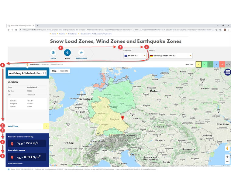
The Dlubal online service Snow Load Zones, Wind Zones, and Earthquake Zones combines the standard specifications with digital technologies. The service places the respective zone map over the Google Maps map, depending on the selected load type (snow, wind, earthquake) and the country-specific standard. Enter the location, geographic coordinates, or local conditions in the search function to get the relevant data. The tool then determines the characteristic load or acceleration at this location by means of the exact height above sea level and the zone data entered. If it is impossible to define the location by means of a specific address, you can zoom into the map and select the correct location. When selecting the correct location on the map, the calculation will be adapted to the new altitude and will display the updated loads.
The online service is available on the Dlubal website at Solutions → Online Services.
By defining the parameters...
1. load type = wind
2. standard = EN 1991-1-4
3. Annex = Germany | DIN EN 1991-1-4
4. Address = Zellweg 2, Tiefenbach
...it results in the following for the selected location:
5. the wind zone
6. additional information, if applicable
7. fundamental basic wind velocity vb,0
8. basic wind velocity pressure qb
If you select a position above 1,100 m, the online service displays at point 6 "No defined wind load above 1,100 m | NCI A.2 (3)". No load can be determined according to the existing rule, and special considerations are required for this location.
Wind Pressure on Surfaces
The acting wind pressure on a surface is the product of governing peak velocity pressure multiplied by the aerodynamic coefficient [1], [2].
For external surfaces:
we =qp(ze) ⋅ cpe
where
qp(ze) = peak velocity pressure
ze = reference height for the external pressure
cpe = aerodynamic coefficient for the external pressure
For internal surfaces:
wi =qp(zi) ⋅ cpi
where
qp(zi) = peak velocity pressure
zi = reference height for the internal pressure
cpi = aerodynamic coefficient for the internal pressure
The resulting loading of external and internal pressure is the net pressure loading on a surface. The pressure on a surface is considered as positive and the pressure (suction) away from the surface as negative.
Net pressure:
wnet = we + wi

Selected Aerodynamic Coefficients
Pressure and suction loads are applied on the surface of a structure that is in the wind flow. The size of the action on the external surfaces depends on their load application area. A load application area is the surface that absorbs the flat wind loading actively and transmits it in a concentrated way to the structural system below. For this type of analysis, the standard contains aerodynamic external pressure coefficients that depend on the load introduction surface [1], [2].
| Load Application Area A [3] | Aerodynamic External Pressure Coefficient cpe | Description |
|---|---|---|
| < 1 m² | cpe,1 | Design of small structural components and their anchorages (for example, encasement or roof elements) |
| 1 m² to 10 m² | cpe,1 - (cpe,1 - cpe,10) ⋅ log10(A) | |
| > 10 m² | cpe,10 | Design of the entire structure |
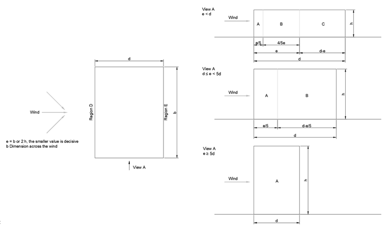
Vertical Walls of Buildings with Rectangular Floor Plan
The wind velocity naturally increases nonlinearly with the height from the ground. The resulting peak velocity pressure distribution can be applied in a simplified and scaled manner by the height for the windward building surface (windward area D), depending on the ratio building height h to building width b [1], [2].
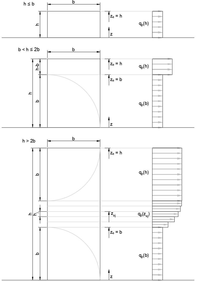
The wall suction loads of the remaining leeward building surfaces parallel to the wind (areas A, B, C, and E) depend on the aerodynamics of the building. The final aerodynamic coefficients for the external surfaces can be determined and applied in a scaled manner, depending on the ratio building height h to building depth d.
| Area | A | B | C | D | E | |||||
|---|---|---|---|---|---|---|---|---|---|---|
| h/d | cpe,10 | cpe,1 | cpe,10 | cpe,1 | cpe,10 | cpe,1 | cpe,10 | cpe,1 | cpe,10 | cpe,1 |
| ≥5 | -1.4 | -1.7 | -0.8 | -1.1 | -0.5 | -0.7 | +0.8 | +1.0 | -0.5 | -0.7 |
| 1 | -1.2 | -1.4 | -0.8 | -1.1 | -0.5 | +0.8 | +1.0 | -0.5 | ||
| ≤0.25 | -1.2 | -1.4 | -0.8 | -1.1 | -0.5 | +0.8 | +1.0 | -0.3 | -0.5 | |
| Larger suction forces may occur in the suction area for detached buildings located at open area sites. Linear interpolation of the intermediate values is allowed. For buildings with h/d> 5, the entire wind load has to be determined by means of the force values according to DIN EN 1991-1-4 plus National Annex of Germany Chapters 7.6 to 7.8 and 7.9.2. | ||||||||||
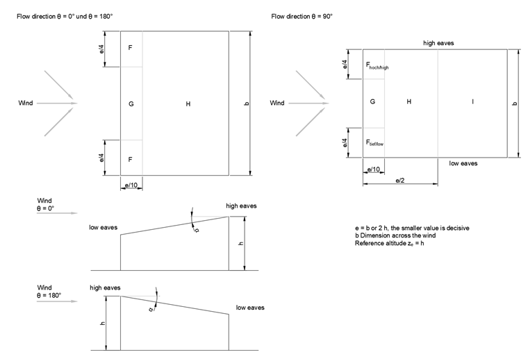
Monopitch Roof
Similar to the dimensions of the building, the shape of the roof also has an aerodynamic effect on the external roof surfaces. A roof with an inclination greater than 5° with distinctive high and low eaves is called a monopitch roof. Due to the aerodynamics, wind loads are acting on the load application surfaces, depending on the roof inclination [1], [2].
| Area | F | G | H | I | ||||||
|---|---|---|---|---|---|---|---|---|---|---|
| Flow direction θ = 0°2) | ||||||||||
| Inclination angle α1) | cpe,10 | cpe,1 | cpe,10 | cpe,1 | cpe,10 | cpe,1 | cpe,10 | cpe,1 | ||
| 5° | -1.7 | -2.5 | -1.2 | -2.0 | -0.6 | -1.2 | - | - | ||
| +0.0 | +0.0 | +0.0 | ||||||||
| 15° | -0.9 | -2.0 | -0.8 | -1.5 | -0.3 | - | - | |||
| +0.2 | +0.2 | +0.2 | ||||||||
| 30° | -0.5 | -1.5 | -0.5 | -1.5 | -0.2 | - | - | |||
| +0.7 | +0.7 | +0.4 | ||||||||
| 45° | -0.0 | -0.0 | -0.0 | - | - | |||||
| +0.7 | +0.7 | +0.6 | ||||||||
| 60° | +0.7 | +0.7 | +0.7 | - | - | |||||
| 75° | +0.8 | +0.8 | +0.8 | - | - | |||||
| Flow direction θ = 180° | ||||||||||
| 5° | -2.3 | -2.5 | -1.3 | -2.0 | -0.8 | -1.2 | - | - | ||
| 15° | -2.5 | -2.8 | -1.3 | -2.0 | -0.9 | -1.2 | - | - | ||
| 30° | -1.1 | -2.3 | -0.8 | -1.5 | -0.8 | - | - | |||
| 45° | -0.6 | -1.3 | -0.5 | -0.7 | - | - | ||||
| 60° | -0.5 | -1.0 | -0.5 | -0.5 | - | - | ||||
| 75° | -0.5 | -1.0 | -0.5 | -0.5 | - | - | ||||
| Flow direction θ = 90° | ||||||||||
| Fhigh | Flow | |||||||||
| cpe,10 | cpe,1 | cpe,10 | cpe,1 | |||||||
| 5° | -2.1 | -2.6 | -2.1 | -2.4 | -1.8 | -2.0 | -0.6 | -1.2 | -0.5 | |
| 15° | -2.4 | -2.9 | -1.6 | -2.4 | -1.9 | -2.5 | -0.8 | -1.2 | -0.7 | -1.2 |
| 30° | -2.1 | -2.9 | -1.3 | -2.0 | -1.5 | -2.0 | -1.0 | -1.3 | -0.8 | -1.2 |
| 45° | -1.5 | -2.4 | -1.3 | -2.0 | -1.4 | -2.0 | -1.0 | -1.3 | -0.9 | -1.2 |
| 60° | -1.2 | -2.0 | -1.2 | -2.0 | -1.2 | -2.0 | -1.0 | -1.3 | -0.7 | -1.2 |
| 75° | -1.2 | -2.0 | -1.2 | -2.0 | -1.2 | -2.0 | -1.0 | -1.3 | -0.5 | |
| 1) Linear interpolation of the intermediate values is allowed, provided that the sign does not change. The value of 0.0 is given for the interpolation. 2) For the flow direction θ = 0° and the inclination angles α = +5° to +45°, the pressure changes very quickly between positive and negative values. Therefore, the positive as well as the negative external pressure coefficient is given for this area. For such roofs, both cases (pressure and suction) have to be considered separately by considering first, only the positive values (pressure), and second, only the negative values (suction). | ||||||||||
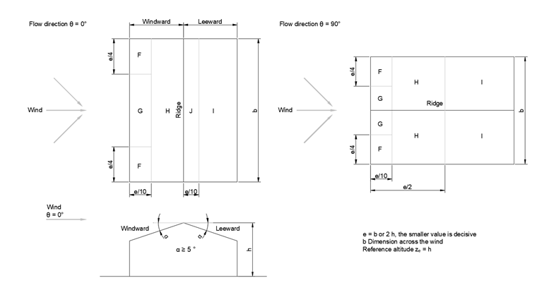
Duopitch Roof
A roof shape consisting of two roof surfaces inclined in opposite directions that intersect at the upper horizontal edge in the roof ridge is called a duopitch roof. This geometry has its own aerodynamic effects on the load application areas [1], [2].
| Area | F | G | H | I | J | ||||||
|---|---|---|---|---|---|---|---|---|---|---|---|
| Flow direction θ = 0°2) | |||||||||||
| Inclination angle α1) | cpe,10 | cpe,1 | cpe,10 | cpe,1 | cpe,10 | cpe,1 | cpe,10 | cpe,1 | cpe,10 | cpe,1 | |
| 5° | -1.7 | -2.5 | -1.2 | -2.0 | -0.6 | -1.2 | -0.6 | +0.2 | |||
| +0.0 | +0.0 | +0.0 | -0.6 | ||||||||
| 15° | -0.9 | -2.0 | -0.8 | -1.5 | -0.3 | -0.4 | -1.0 | -1.5 | |||
| +0.2 | +0.2 | +0.2 | +0.0 | +0.0 | +0.0 | ||||||
| 30° | -0.5 | -1.5 | -0.5 | -1.5 | -0.2 | -0.4 | -0.5 | ||||
| +0.7 | +0.7 | +0.4 | +0.0 | +0.0 | |||||||
| 45° | -0.0 | -0.0 | -0.0 | -0.2 | -0.3 | ||||||
| +0.7 | +0.7 | +0.6 | +0.0 | +0.0 | |||||||
| 60° | +0.7 | +0.7 | +0.7 | -0.2 | -0.3 | ||||||
| 75° | +0.8 | +0.8 | +0.8 | -0.2 | -0.3 | ||||||
| Flow direction θ = 90° | |||||||||||
| 5° | -1.6 | -2.2 | -1.3 | -2.0 | -0.7 | -1.2 | -0.6 | - | - | ||
| 15° | -1.3 | -2.0 | -1.3 | -2.0 | -0.6 | -1.2 | -0.5 | - | - | ||
| 30° | -1.1 | -1.5 | -1.4 | -2.0 | -0.8 | -1.2 | -0.5 | - | - | ||
| 45° | -1.1 | -1.5 | -1.4 | -2.0 | -0.9 | -1.2 | -0.5 | - | - | ||
| 60° | -1.1 | -1.5 | -1.2 | -2.0 | -0.8 | -1.0 | -0.5 | - | - | ||
| 75° | -1.1 | -1.5 | -1.2 | -2.0 | -0.8 | -1.0 | -0.5 | - | - | ||
| 1) For the flow direction θ = 0° and the inclination angles α = -5° to +45°, the pressure changes very quickly between positive and negative values. Therefore, the positive as well as the negative value is indicated. For such roofs, four cases have to be considered, where the smallest or largest value for areas F, G, and H is combined with the smallest or largest values for areas I and J. Positive and negative values cannot be mixed on a roof surface. 2) For roof inclinations between the indicated values, linear interpolation is allowed, provided that the sign of the pressure coefficients does not change. For inclinations between α = +5° and -5°, the values for flat roofs have to be used according to DIN EN 1991-1-4 plus Chapter 7.2.3. The value of zero is given for the interpolation. | |||||||||||