


Description
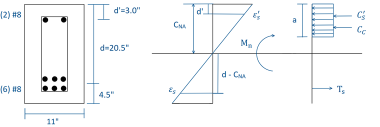
The doubly reinforced concrete beam section found in Figure 01 will be designed under ULS according to ACI 318-14 [1] using factored LRFD load combinations. An unfactored uniform dead load and live load of 2.0 kip/ft and 3.2 kip/ft, respectively, are applied to the beam. The selected rectangular beam has an overall cross-section of 25 inches ⋅ 11 inches. The concrete material has a compression strength (f'c) of 5,000 psi while the reinforcing steel has a yield strength (fy) of 60,000 psi. The compression reinforcement (A's) consists of two #8 bars with a centroid distance (d') of 3.0 inches from the top compression fiber with a total area of 1.57 in². The tensile reinforcement (As) consists of six #8 bars with a centroid distance (d) of 20.5 inches from the top compression fiber with a total area of 4.71 in². The shear reinforcement (Av) includes #4 stirrups for a total area of 0.4 in². The dimensions and stress/strain diagram of the beam cross-section are shown in Figure 01.
Moment Strength
The required nominal moment, Mu, from the applied loads is found to be 4512.00 kip-in. Deriving the equation to find the nominal moment requires the following assumptions.
Compression steel does not yield: ε's < εy → f's = Es ⋅ ε's
Tensile steel does yield: εs ≥ εy → fs = fy
Analyzing the stress and strain diagram of the beam, the neutral axis can be found with the equation below. The equation is derived by setting the compression forces equal to the tension forces in order to satisfy equilibrium:
Ts = C's + Cc → As ⋅ fy - A's ⋅ f's - 0.85 ⋅ f'c ⋅ a ⋅ b = 0
Utilizing the strain diagram and similar triangles, we can assume:
We also know: a = β1 ⋅ CNA
Substituting β1 ⋅ CNA and
for a and ε's, respectively, into the equilibrium equation above, the neutral axis can be calculated, as all values are known except CNA.Using Table 22.2.2.4.3 from ACI 318 - 14 [1], β1 is equal to 0.80. Solving for CNA, we find it is equal to about 5.83 inches from the top extreme compression fiber.
The above assumptions (1 and 2) must be verified. Assumption 1 consists of calculating the strain in the compression steel (ε's) and comparing it with the yield strain (εy). If ε's is less than εy, our assumption is correct. Assumption 2 requires calculating the strain of the tensile steel reinforcement (εs) and comparing it to εy. If εs is greater than εy, then our assumption is correct. We verify through calculation (not shown) that assumptions 1 and 2 are valid.
Finally, to solve for the nominal moment (Mn), we set the sum of moments about the location of the concrete in compression (Cc) equal to zero. This can be seen in the diagram from Figure 01.
This equation becomes:
Before we can solve for Mn, we must substitute C's and Ts for
and As ⋅ fy, respectively.The equation becomes:
We must also calculate a by multiplying β1 and CNA together before calculating Mn.
a = 4.66 in
By substituting these values into the Mn equation, we get the following:
Mn is calculated as 5122.69 kip-in.
Finally, the safety factor (φ) is determined by referencing Table 21.2.2 from ACI 318 -14 [1]. To determine φ, the tension strain is compared to the ultimate strain of 0.005. εt is equal to 0.00755 and is greater than 0.005. The beam is tension controlled. From Table 21.2.2, φ is equal to 0.90. When multiplying this factor by Mn, φMn is equal to 4610.42 kip-in. Therefore, the moment capacity of the beam is sufficient to resist the applied bending moment.
φMn > Mu = 4512.00 kip-in o.k.
Shear Strength
Note: The effective depth (d) for the shear design calculations is taken as 22.5 inches opposed to the 20.5 inches set forth in the problem statement. The location of the max shear force is also the location of minimal bending moment (face of the support). To correlate the analytical calculations to the reinforcement design in RF-CONCRETE Members, the add-on module bases the effective depth on the required tension reinforcement rather than provided tension reinforcement. Therefore, with minimal bending moment at the support face, only one layer of tension reinforcement is required, given an effective depth of 22.5 inches.
Based on Sec. 22.5.1.1 [1], we calculate the nominal shear strength (Vn) of the beam. The following equation is used to calculate nominal shear:
Vn = φ ⋅ (Vc + Vs)
Referencing Table 22.5.5.1 [1], concrete shear strength Vc is equal to the minimum of equations a, b, and c calculated in Sections 1, 2, and 3 below.
1. Equation a is given as:
Mu occurs at Vu which is distance d away from the support face (Section 9.4.3.2 [1]). Therefore, Mu is equal to 1533.38 kip-in. Vu = 61.10 kips.
Vc-a = 44.96 kips
2. Equation b is given as:
Vc-b = 46.26 kips
3. Equation c is given as:
Vc-c = 61.25 kips
Therefore, selecting the minimum value from the equations above, we find Vc is equal to 44.96 kips.
Following the nominal shear of the concrete calculation, the minimum shear reinforcement is found utilizing Sec. 9.6.3 [1]. Here, if the required shear strength Vu is less than 0.5 ⋅ φ ⋅ Vc, then shear reinforcement is required.
Vu < 0.5 ⋅ φ ⋅ Vc
Where,
φ = 0.75 (Table 21.2.1 [1])
Therefore, Vu = 61.10 kips > 16.86 kips. Stirrups are required.
The theoretical spacing is determined from Sec. 9.5.1.1 [1]:
φ ⋅ Vn > Vu
We substitute (Vc + Vs) for Vn.
So, Vs > 36.51 kips.
From Sec. 22.5.10.5.3 [1], we use the following equation to calculate the required steel shear strength:
Where, fyt is the yield strength of the steel reinforcement in tension and d is the distance from the top compression fiber to the centroid of the tension reinforcement.
The max spacing(s) is calculated to be 14.79 inches. A spacing of 14 inches for the shear reinforcement is used. Using a spacing of s = 14 inches, the above equation for steel shear strength, Vs, is calculated to be 38.57 kips.
Using Table 9.7.6.2.2 [1], the maximum shear spacing must be determined. The following equation is calculated to determine which equation in Table 9.7.6.2.2 is applicable:
The steel shear strength, Vs = 38.57 kips, is less than the calculated value of 70.00 kips. Referencing Table 9.7.6.2.2, the maximum shear spacing can be determined using the minimum value from the following calculations:
The maximum shear spacing is determined to be 11.25 inches. The shear spacing determined previously with #4 bars spaced at 14 inches is not sufficient, and 11 inches should be used instead. We verify that the nominal shear capacity is greater than the required ultimate shear strength to ensure that the shear reinforcement and spacing are adequate. With respect to our new max spacing of 11 inches, we receive a Vs value of 49.09 kips.
Vn = φ ⋅ (Vc + Vs) = 0.75 ⋅ (44.96 + 49.09) > Vu= 61.10 kips
Vn = 70.54 > 61.10 kips
The final verification includes determining whether the cross-section dimensions are sufficient based off Sec. 22.5.1.2. [1]. To do this, ultimate shear strength is compared to Eqn. 22.5.1.2 from ACI 318-14 [1]:
This value of 105.04 kips is greater than Vu. Therefore, the current cross-section dimensions are sufficient.
Results
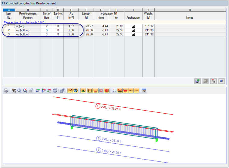
An alternative for concrete reinforcement design is to utilize the add-on module RF-/CONCRETE Members and perform the design as per ACI 318-14 [1]. The module will determine the required reinforcement to resist the applied loads on the beam. Furthermore, the program will also design the provided reinforcement based on the specified bar sizes set by the user while taking into consideration spacing requirements from the standard. The user has the opportunity to make small adjustments to the provided reinforcement layout in the results table.
Based on the applied loads for this example, RF-CONCRETE Members has determined a required minimum tension reinforcement of 4.46 in² and a provided reinforcement of (6) #8 bars (As = 4.72 in²). This reinforcement layout is shown in Figure 02.
The required shear reinforcement for the member within RF-CONCRETE Members was calculated to be 0.41 in²/ft. To meet this minimum area and provide uniform stirrup spacing along the length of the 20 ft beam, the program has recommended #4 bars at 10.91 inch spacing. The shear reinforcement layout is shown in Figure 03.
