Graphical/Tabular Creation of User-defined Cross-sections in RSECTION 1
Technical Article
RSECTION 1 is a stand-alone program for determining section properties for both thin-walled and massive cross-sections, as well as for performing a stress analysis. In addition, the program can be connected to both RFEM and RSTAB: sections from RSECTION are available in the RFEM/RSTAB libraries, and internal forces from RFEM/RSTAB can be imported into RSECTION.
The user-defined cross-section in RSECTION 1 can be created by entering data using various methods: graphically, in tables, via script, or by importing a DXF file. This article will show the basis of defining cross-sections in graphical and tabular form.
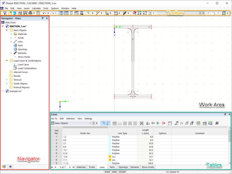
Graphical tools and functions in RSECTION allow modeling complex section shapes in the usual method common for CAD programs. The graphical input supports, among other things, the settings of arcs, circles, ellipses, parabolas, and NURBS. Furthermore, the user interface is very similar to that of RFEM/RSTAB: it includes the working window, navigator, tables, and toolbar (Image 1).
In the same fashion as in RFEM 6, you can define basic objects such as materials, points, lines, parts, openings, elements, and stress points using the Data tab of the Navigator. The material library is available to import materials, but you can also define it yourself.
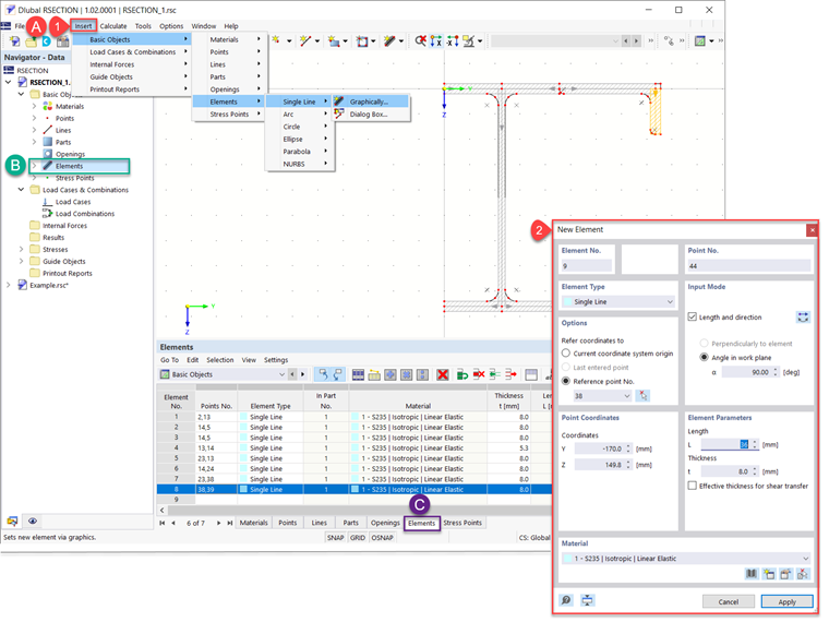
As a matter of fact, cross-sections in RSECTION 1 are generated as an assembly of elements defined as single lines, arcs, circles, ellipses, parabolas, and NURBS. They can be defined graphically via the toolbar as shown in Image 2. Additionally, you can define them by the dialog box available via the toolbar, the navigator, and the tables.
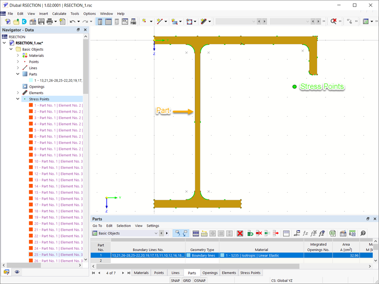
The defined elements must always lie in a surface called a "part". If the elements are created graphically, parts are created automatically. If, on the other hand, they are created via a dialog box, parts must be created beforehand. You can define parts by selecting their boundary lines, as shown in this article’s video. Cross-sectional properties such as cross-sectional area and moment of inertia are calculated on the basis of defining the parts. Finally, stress points are generated automatically by defining the parts (Image 3); nevertheless, they can be defined manually as well.
Once the cross-section has been defined and the stress points have been generated, you can initiate the analysis and calculate the stresses on the effective cross-section. The stress analysis in RSECTION 1 will be considered in an upcoming Knowledge Base article.
Author

Irena Kirova, M.Sc.
Marketing & Customer Support
Ms. Kirova is responsible for creating technical articles and provides technical support to the Dlubal customers.
Keywords
Links
- Product Description | RSECTION 1
- Recorded Webinar | Section Properties Determination and Stress Analysis in RSECTION 1
Write Comment...
Write Comment...
Contact Us
Do you have further questions or need advice? Contact us via phone, email, chat, or forum, or find suggested solutions and useful tips on our FAQ page, available 24/7.

New
Thin-Walled Analysis in RSECTION 1
This article is discussing the thin-walled analysis method in RSECTION 1, with which the section properties for both gross and effective cross-sections are calculated analytically (based on the section’s elements).

RSECTION contains an extensive library of rolled sections, as well as parametric thin-walled and massive cross-sections. They can be composed or complemented by new elements.
Graphical tools and functions allow for modeling complex section shapes in the usual way common for CAD programs. The graphical input supports, among other things, the setting of arcs, circles, ellipses, parabolas, and NURBS. As an alternative, it is possible to import a DXF file that is used as the basis for further modeling. It is possible to model a cross-section consisting of different materials.
Furthermore, a parameterized input allows you to enter the cross-section dimensions and internal forces in such a way that they depend on certain variables.
All inputs can also be done by means of scripts.
-
The limit stress is activated, but my stress ratio is “non-designable” in the Stress-Strain Analysis add-on. What could be the reason?
- Is it possible to calculate the weld stresses between surfaces with RFEM 6?
- Is it possible to display the deformation analysis of a surface (limit 0.5‰)?
- For the settlement calculation in the RF‑SOILIN add-on module, the specific weight gamma and gamma,sat are required for the soil. What do I need the value gamma,sat for, and how is it assumed in the calculation?
- How does the "Orthotropic Plastic" material model work in RFEM?
- I would like to define a line support with ineffective tension and apply the tension force on this line using a nodal support instead. Why does the line support still receive a tension force?
- Is it possible to consider the reduction of strength in the heat affected zone (HAZ) in the RF‑/ALUMINUM add-on module?
- The design ratio of the cross-section check is different for the RF‑/STEEL and RF‑/STEEL EC3 add-on modules. What is the reason?
- What is the difference between SHAPE‑THIN 9 and SHAPE‑THIN 8?
- How do I display some results of all load cases in the printout report, but other results of selected load cases only?
Associated Products