What does tension for a concrete element mean?
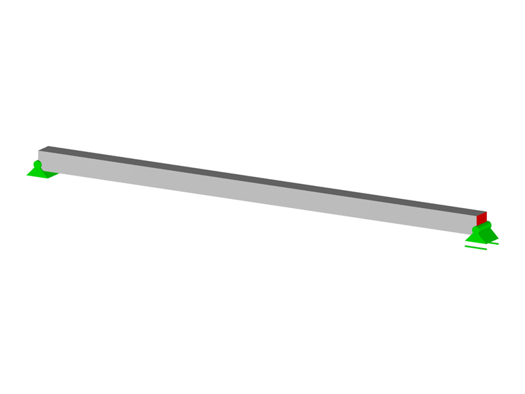
A section of a structural element is stressed by simple tension when the forces acting on one side of the section are reduced at the section's center of gravity to a single force N. This normal force N is then perpendicular to the section and directed towards the side where the forces act. The self-weight is neglected in the concrete and the section is uniformly subjected to tension.
Tensile Stress in Steel
For steel with a σ – ε diagram showing an inclined graph, the equation to the right of the graph corresponding to the tensile behavior of steel is written according to the steel's characteristic values set forth in §3.2. 7 (2) of EN 1992-1-1.
|
σs |
Contrainte dans l'armature |
|
fyd |
Limite d'élasticité de calcul = fyk / γs |
|
k |
Rapport des limites caractéristiques = ftk / fyk |
|
εuk |
Déformation limite |
|
Es |
Module d'élasticité |
|
εs |
Déformation dans l'armature = εud = 0,9 ⋅ εuk |
|
fyk |
Limite d'élasticité caractéristique |
|
γs |
Coefficient partiel de l'acier |
|
ftk |
Valeur caractéristique de la résistance en traction |
|
εud |
Déformation limite de calcul |
Longitudinal Reinforcement
Please note: the concrete under tension is neglected for pure tension. In this case, only the steel fully balances the tensile force NEd . Thus, the necessary reinforcement area is determined according to the tensile force and the provided stress.
As = NEd / σs
As … Reinforcement area
NEd … Ultimate normal force
Application of Theory Using RF-CONCRETE Members
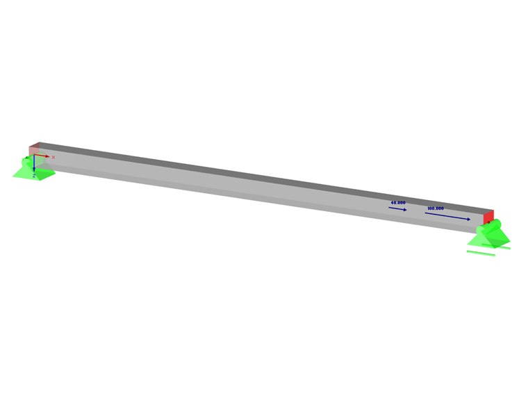
We look at an example of an element subjected to simple tension by analyzing the results obtained for the longitudinal reinforcements. You will find the input data below:
- Permanent loads: Ng = 100 kN
- Variable loads: Nq = 40 kN
- Square section: 20/20 cm
- Concrete strength class: C25/30
- Steel: S 500 A for inclined graph
- Diameter of longitudinal reinforcement: ϕl = 12 mm
- Diameter of transverse reinforcement: ϕt = 6 mm
- Concrete cover: 3 cm
- Control of cracking not required.
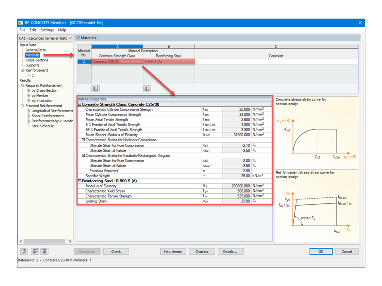
In order to verify the material settings in RF-CONCRETE Members, Image 02 describes the materials used for concrete and reinforcement.
Ultimate Limit State
Design loading in the ultimate limit state:
NEd = 1.35 ⋅ 100 + 1.5 ⋅ 40 = 195.00 kN
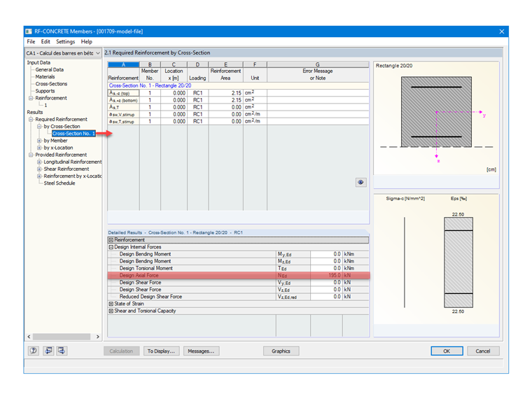
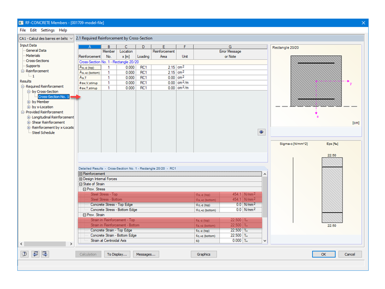
Provided Tensile Stress
Ultimate limit state for a durable, transient design situation:
fyd = 500 / 1.15 = 435 MPa
k = 525 / 500 = 1.05 according to Table C.1 of EN 1992-1-1
εuk = 25‰
εud = 0.9 ⋅ 25 = 22.5‰
σs = 435 + (1.05 ⋅ 435 - 435) / (2.5 - 435 / (200,000)) ⋅ [2.25 - 435 / (200,000)] = 454 MPa
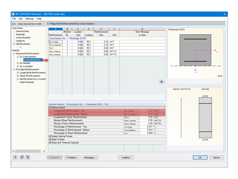
Required Longitudinal Reinforcement
Longitudinal reinforcements for the ultimate limit state:
As = 0.195 / 454 ⋅ 104 = 4.30 cm²
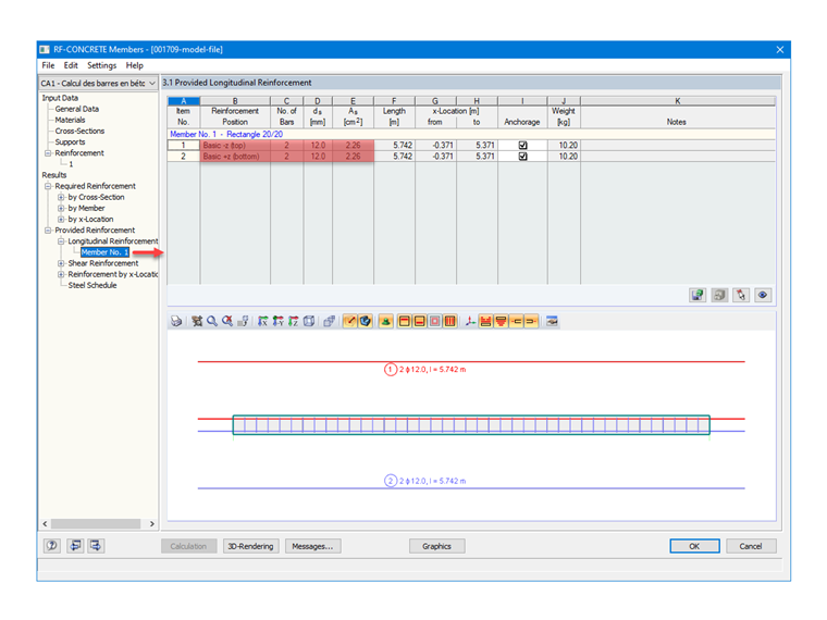
Provided Longitudinal Reinforcement
Having configured the reinforcing steel with a diameter of 12 mm in RF-CONCRETE Members, the provided reinforcement determined automatically by the add-on module is 4 bars, with symmetrical distribution on the lower and upper parts of the section; that is, 2 x 2 HA12, which results in the following reinforcement area:
As = 4 ⋅ 1.13 = 4.52 cm²
Transverse Reinforcement
With the transverse reinforcement also having been defined by the user, RF-CONCRETE Members can automatically determine the spacings according to the standard, and check whether their arrangement conforms.
In our case, by imposing stirrups with a diameter of 6 mm, the program gives us a spacing of 0.122 m, but also displays warning message No. 155) in the Notes column that can be seen in Image 07.
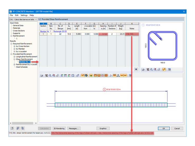
The formula referring to §9.2.2 (8) of EN 1992-1-1 is defined below.
Sl,max = 0.75 ⋅ d
Sl,max … Maximum transverse spacing of stirrups
d … Effective height
d = h - e - ∅t - ∅l/2
h … Cross-section depth
e … Concrete cover
The previous formulas give us the following results:
d = 0.200 - 0.03 - 0.006 - 0.012 / 2 = 0.158 m
Sl,max = 0.75 ⋅ 0.158 = 0.12 m
Therefore, warning message 155 appears because the spacing between the stirrup legs of a beam in the transverse direction exceeds the limit value given by the standard. The problem can be solved by increasing the number of stirrup legs in the settings for the stirrup reinforcement, as detailed in this FAQ.
Conclusion
Having set the parameters beforehand, RF-CONCRETE Members gives the number of rebars required according to the defined arrangement, in order to verify the tensile load according to the internal forces coming from RFEM. Depending on the warning messages displayed, it is also possible for the user to modify the reinforcement and its arrangement after the calculation.