An earlier technical article describes how to determine the material properties of steel fiber-reinforced concrete and convert these material parameters in the FEA software RFEM.
Pure steel fiber-reinforced concrete is mainly used for industrial floors and moderately loaded foundation plates. A linear elastic determination of internal forces does not provide any economical results for purely fiber-reinforced structural components. Therefore, plastic methods are usually used for the ultimate limit state. However, these plastic approaches are rather unsuitable for the serviceability limit state. A nonlinear FEM calculation is always possible, regardless of the analyzed limit state. We perform the design manually, based on the iteratively determined internal forces.
Entering Topology and Loads
The floor slab is entered as a foundation surface. For the foundation slab of this technical article, the foundation is realized with the "effective soil" method according to Kolar and Nemec [3]. The adjacent soil is taken into account by additional line springs and single springs in the corners (see also the following article).
You can also calculate the surface elastic foundation with the RF-SOILIN add-on module.
The ultimate limit state design is shown by the loads from the shelf supports and the load under the shelves. The shelf support loads are defined as free rectangular loads. Additionally, points with mesh refinements have been arranged on the shelf supports so that the load is distributed into the base plate distributed over several elements.
Defining Material Properties
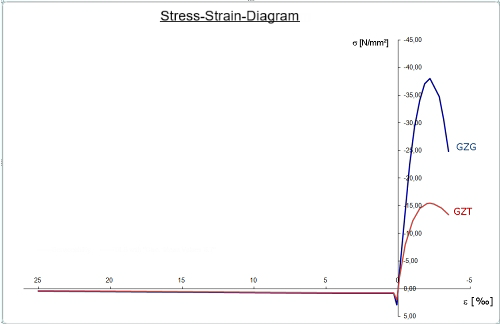
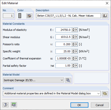
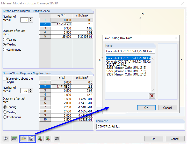
Use the "Isotropic Damage 2D/3D" material model of the RF-MAT NL add-on module to display the material behavior of steel fiber-reinforced concrete in RFEM. We use C30/37 L1.2/L0.9 concrete as steel fiber-reinforced concrete in accordance with DIN EN 1992-1-1 [2] and the guideline by the German Committee for Reinforced Concrete (DAfStb) on steel fiber-reinforced concrete [1] with the two performance classes L1/L2 = L1.2/L0.9. For a nonlinear calculation, the parabolic curve according to 3.1.5 [2] must be used on the compression side of the stress-strain diagram. The following image shows the characteristic curve of the working line of the aforementioned steel fiber-reinforced concrete.
We have to use the characteristic stress-strain curve for the serviceability limit state. For the nonlinear calculation of the ultimate limit state, you have to apply the following according to Chapter 5.7 of the guideline by the German Committee for Reinforced Concrete (DAfStb) on steel fiber-reinforced concrete [1]:
|
1.04 ⋅ ffcrLi |
Rechnerischer Mittelwert der vom Stahlfaserbeton nach der Rissbildung aufnehmbaren Zugbeanspruchung gemäß den Leistungsklassen L1 oder L2 |
|
fcR, fyR, ftR |
Jeweiliger rechnerischer Mittelwert der Festigkeit des Betons nach NA.10, DIN EN 1992-1-1 |
|
γR |
Teilsicherheitsbeiwert für den Systemwiderstand |
For pure steel fiber-reinforced concrete components, γR is assumed to be 1.4.
The partial safety factor γR can be considered either on the resistance side, when entering the material properties, or on the action side. In this article, we apply the global partial safety factor γR directly when defining the nonlinear working line. Image 03 shows the reduced stress-strain curve for the ultimate limit state design in comparison with the characteristic working line for the SLS.
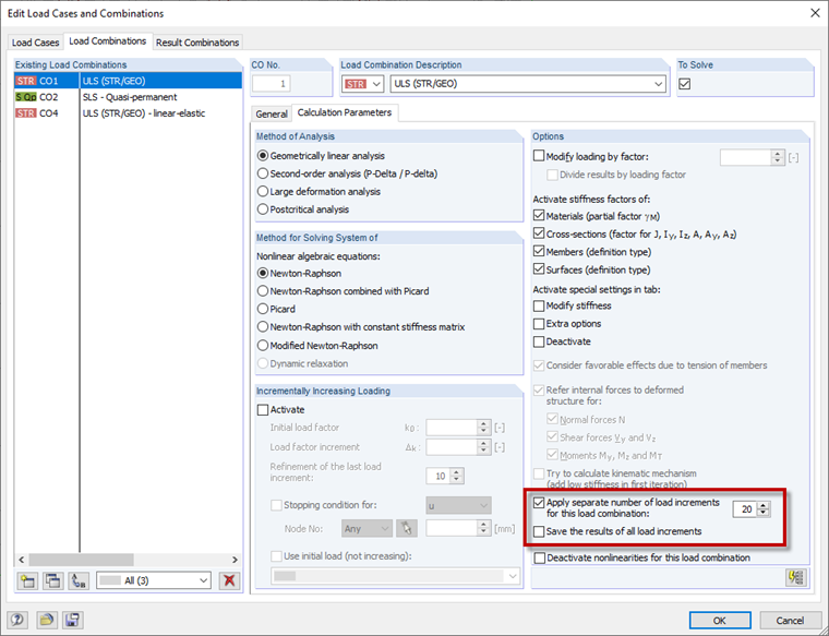
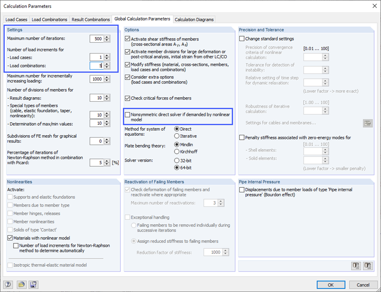
For nonlinear calculations, you have to apply the load step by step. If the calculation of a load increment does not converge within the preset maximum number of iteration steps, increase the maximum number of iteration steps in the calculation parameters. In addition, you can achieve better convergence when using a nonlinear material model by selecting the asymmetrical equation solver in the calculation parameters.
Ultimate Limit State Design
The ultimate limit state is considered to be reached if
- The critical ultimate strains of the steel fiber-reinforced concrete εcu1 on the compression side and εfct,u on the tension side are reached.
- The critical state of the indifferent equilibrium is reached in the entire system or in parts of it.
After successful nonlinear calculation of the base plate, the maximum and minimum strains on the top and bottom sides are checked. If the critical ultimate strains are not exceeded, the ultimate limit state design is performed.
Subsequent strains were calculated for the ultimate limit state.
Top side:
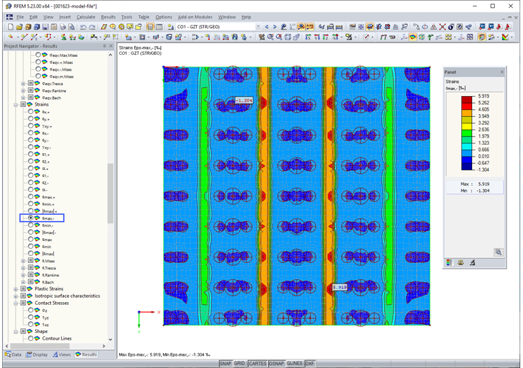
- Maximum compression strain εmin- = -1.9‰ < 3.5‰
- Maximum tensile strain εmax- = 4.2‰ < 25.0‰
Bottom side:
- Maximum compression strain εmin+ = -1.05‰ < 3.5‰
- Maximum tensile strain εmax+ = 9.9‰ < 25.0‰
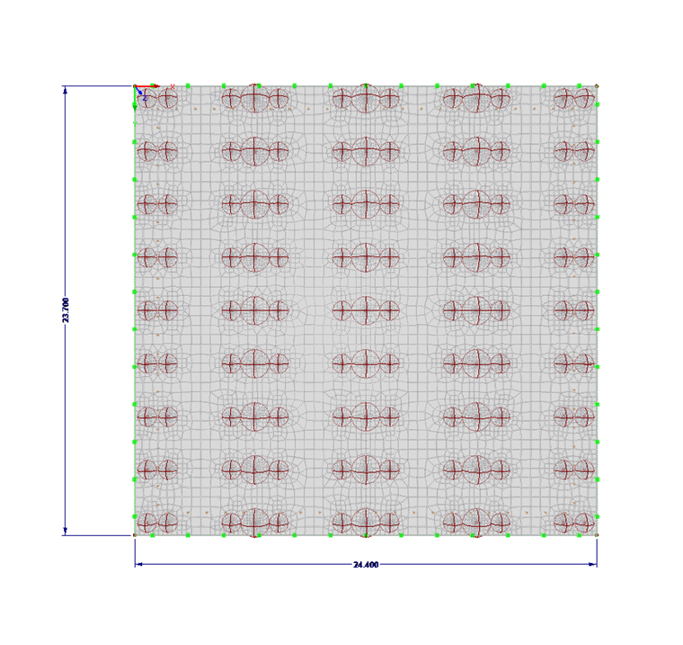
Image 05 shows the maximum distortion at the top (-z) of the foundation plate.
By adhering to the limit strains, it was possible to successfully determine the ultimate limit state subjected to bending. We have to perform additional ultimate limit state design checks; for example, punching.
Recommendations for Nonlinear Calculation with "Isotropic Damage 2D/3D" Material Model
Based on the polygonal definition of the stress-strain curve as a diagram, RFEM expects the tangent modulus at the origin of the stress-strain curve as the modulus of elasticity of the steel fiber-reinforced concrete. This means that you have to adjust the preset secant modulus for concrete as well, when entering the steel fiber-reinforced concrete work line. The first polygonal point on the compression or tension side of the work line expects the modulus of elasticity of the material as the slope.
An Excel file is attached to this technical article to support you during the input and calculation of the diagram points. In this Excel file, depending on the analyzed limit state (ULS or SLS), you can determine the stress-strain curve to be used and transfer it to the RFEM input dialog box using the clipboard. This approach is also shown in the attached video.
You can save the defined stress-strain diagrams in RFEM and reuse them in other projects. Thus, you can create your own material library of steel fiber-reinforced concrete in RFEM.
Due to the significant nonlinearity, the load should be applied in several load increments. The number of load increments should be selected so that the system remains in the linear elastic state in the first load increment. This improves the convergence behavior of the calculation. You can control the number of load increments globally in the calculation parameters and locally for each load combination or load case. 20 load increments have proven to be advantageous for the iteration for the design load in the ultimate limit state for the floor slab shown above. We defined the 20 load increments locally for the load combination (Image 08).