Click the [Info] button, which is available in all result windows, to view the design details of the selected FE node or grid point, ie the point whose table row the cursor is placed in.

The design details are listed in a tree structure. Die Kapitel lassen sich mit „+“ öffnen und mit „-“ schließen. The buttons shown on the left allow you to [Close] and [Open] the sub-chapters in the directory tree.
In the graphic on the right, the location of the point is shown in the model.
Folgende Details werden beim Nachweis der Tragfähigkeit ausgegeben (siehe Kapitel 2.5):
- Design Report
- Internal Forces of Linear Statics
- Principal Internal Forces
- Design Internal Forces
- Concrete Compression Strut
- Required Longitudinal Reinforcement
- Shear Design
- Statically required longitudinal reinforcement
- Minimum reinforcement
- Check of Maximum Reinforcement Ratio
- Reinforcement to Be Used
- Analysis Method for Reinforcement Envelope
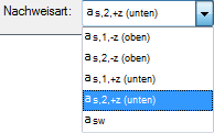
The design details depend on the selected Type of check . Use the list at the bottom of the dialog box to control the displayed results.
In the serviceability limit state design, numerous intermediate results are shown in the lower part of the windows (see Figure 5.6).
Über die [Info]-Schaltfläche ist die ausführliche Liste der Bemessungsdetails zugänglich, die für den aktuellen Punkt vorliegen. This option is only available for results according to the analytical method.
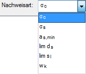
All the design details that are relevant for each type of check are displayed in a tree structure. Use the list at the bottom of the dialog box to control the displayed results.
| Design Method | Design Check Type | |
|---|---|---|
| Analytically | σc | siehe Tabelle 5.2 in Abschnitt 5.4 Gebrauchstauglichkeitsnachweis Gesamt |
| σs | ||
| as,min | ||
| lim ds | ||
| lim sl | ||
| wk |
Mit der Schaltfläche „zurück“ kann zum vorherigen FE- oder Rasterpunkt zurückgeblättert, mit „weiter“ der nächste Punkt eingestellt werden.