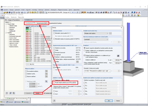
Po kliknutí na tlačítko [Informace], které je k dispozici ve všech výsledkových tabulkách, se zobrazí detaily posouzení vybraného uzlu sítě KP nebo bodu rastru, tedy bodu, v jehož řádku v tabulce se nachází kurzor.

Die Bemessungsdetails sind in einer Baumstruktur aufgelistet. Die Kapitel lassen sich mit „+“ öffnen und mit „-“ schließen. Die beiden links dargestellten Schaltflächen [Schließen] bzw. [Öffnen] die Unterkapitel im Verzeichnisbaum.
Rechts in der Grafik wird die Lage des Punkts im Modell angezeigt.
Folgende Details werden beim Nachweis der Tragfähigkeit ausgegeben (siehe Kapitel 2.5):
- Posudková zpráva
- Schnittgrößen der linearen Statik
- Hlavní vnitřní síly
- Návrhové vnitřní síly
- tlaková diagonála betonu
- Nutná podélná výztuž
- Posouzení na smyk
- Staticky nutná podélná výztuž
- Minimální výztuž
- Kontrola maximálního stupně vyztužení
- Vkládaná výztuž
- Způsob výpočtu pro obálku výztuže
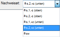
Die Bemessungsdetails sind von der gewählten Nachweisart abhängig. Die Steuerung der angezeigten Ergebnisse erfolgt über die Liste unten im Dialog.
Beim Nachweis der Gebrauchstauglichkeit werden viele Zwischenergebnisse im unteren Bereich der Masken ausgewiesen (siehe Bild 5.6).
Über die [Info]-Schaltfläche ist die ausführliche Liste der Bemessungsdetails zugänglich, die für den aktuellen Punkt vorliegen. Diese Möglichkeit besteht nur für die Ergebnisse nach analytischer Nachweismethode.
In einer Baumstruktur sind alle Bemessungsdetails dargestellt, die für jede Nachweisart relevant sind. Die Steuerung der angezeigten Ergebnisse erfolgt über die Liste unten im Dialog.
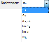
| Metoda posouzení | Typ posudku | |
|---|---|---|
| Analyticky | σc | siehe Tabelle 5.2 in Abschnitt 5.4 Gebrauchstauglichkeitsnachweis Gesamt |
| σs | ||
| as,min | ||
| lim ds | ||
| lim sl | ||
| wk |
Mit der Schaltfläche „zurück“ kann zum vorherigen FE- oder Rasterpunkt zurückgeblättert, mit „weiter“ der nächste Punkt eingestellt werden.


_1.jpg?mw=350&hash=ab2086621f4e50c8c8fb8f3c211a22bc246e0552)


