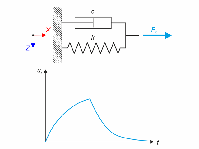
Kelvin-Voigt material model consists of the linear spring and viscous damper connected in parallel. In this verification example there is tested the time behaviour of this model during the loading and relaxation in a time interval 24 hours. The constant force Fx is applied for 12 hours and the rest 12 hours is the material model free of load (relaxation). The deformation after 12 and 20 hours is evaluated. Time History Analysis with Linear Implicit Newmark method is used.
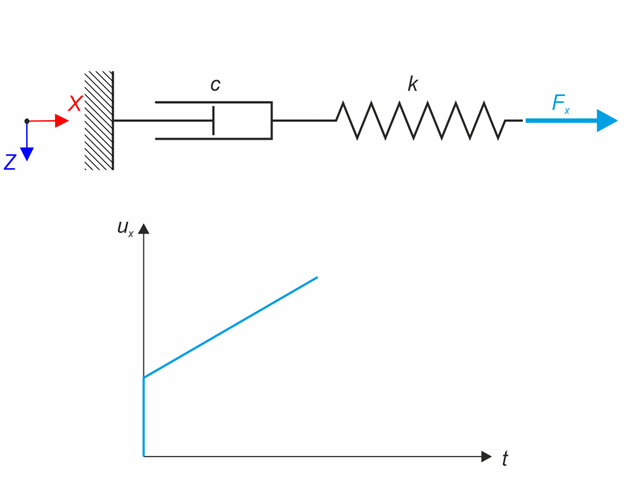
Maxwell material model consists of the linear spring and viscous damper connected in series. In this verification example there is tested the time behaviour of this model. The Maxwell material model is loaded by constant force Fx. This force causes initial deformation thanks to the spring, the deformation is then growing in time due to the damper. The deformation is observed at time of loading (20 s) and at the end of the analysis (120 s). Time History Analysis with Linear Implicit Newmark method is used.

Continuous beam with four spans is loaded by axial and bending forces (replacing imperfections). All supports are fork - warping is free. Determine displacements uy and uz, moments My, Mz, Mω and MTpri and rotation φx. The verification example is based on the example introduced by Gensichen and Lumpe.
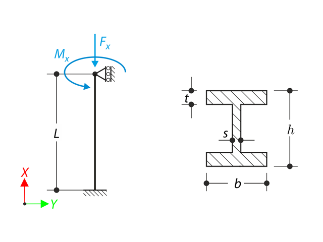
A member with the given boundary conditions is loaded by torsional moment and axial force. Neglecting its self-weight, determine the beam's maximum torsional deformation as well as its inner torsional moment, defined as the sum of a primary torsional moment and torsional moment caused by the normal force. Provide a comparison of those values while assuming or neglecting the influence of the normal force. The verification example is based on the example introduced by Gensichen and Lumpe.
A cantilever is loaded by a moment at its free end. Using the geometrically linear analysis and large deformation analysis, and neglecting the beam's self-weight, determine the maximum deflections at the free end. The verification example is based on the example introduced by Gensichen and Lumpe.
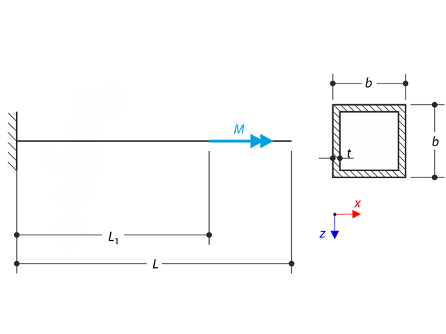
A thin-walled cantilever of a QRO-profile is fully fixed on the left end and warping is free. The cantilever is subjected to torque. Small deformations are considered, and the self-weight is neglected. Determine the maximum rotation, primary moment, secondary moment, and warping moment. The verification example is based on the example introduced by Gensichen and Lumpe.
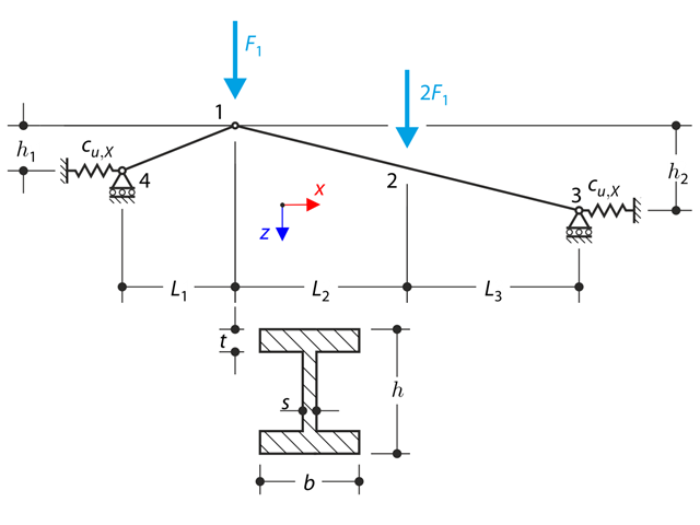
A structure made of I-profile trusses is supported on the both ends by the spring sliding supports and loaded by the transversal forces. The self-we ight is neglected in this example . Determine the deflection of the structure, the bending moment, the normal force in given test points and horizontal deflection of the spring support.
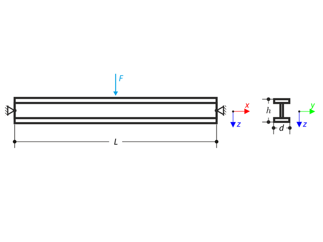
Beam pinned at the both ends is loaded by means the transversal force at the middle. Neglecting its self-weight and shear stiffness, determine the maximum deflection, normal force and moment at the mid-span assuming the second and the third order theory. The verification example is based on the example introduced by Gensichen and Lumpe (see the reference).
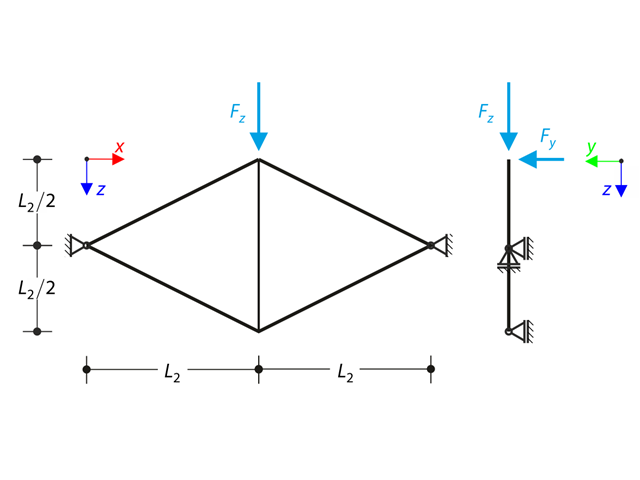
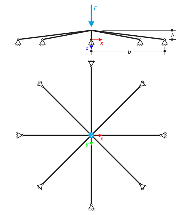
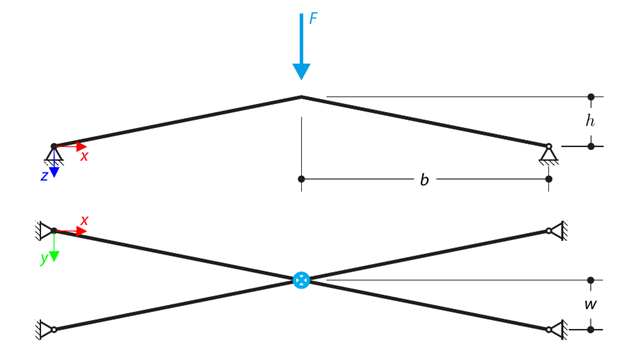
Planar truss consisting of four sloped members and one vertical member is loaded at the upper node by means of the vertical force Fz and out of plane force Fy. Assuming large deformation analysis and neglecting self-weight, determine the normal forces of the members and the out of plane displacement of the upper node uy. The verification example is based on the example introduced by Gensichen and Lumpe.
Das Architectural Institute of Japan (AIJ) hat eine Reihe an bekannten Benchmark-Szenarien für Windsimulation vorgestellt.
Der Nachfolgende Beitrag dreht sich dabei um den "Case A - high-rise building with a 2:1:1 shape".
Im Folgenden wird das beschriebene Szenario in RWIND2 nachgebildet und die Ergebnisse mit den simulierten und der experimentellen Resultate des AIJ verglichen.
A curved frame called Lee's frame is pinned at the end points and loaded by a concentrated force at point A. Determine the deflection ratio at point A in the given load steps. The problem is defined according to The NAFEMS Non-Linear Benchmarks.
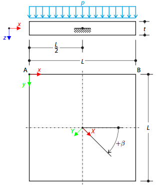
One layered square orthotropic plate is fully fixed at its middle point and subjected to pressure. Compare the deflections of the plate corners to check the correctness of the transformation.
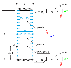
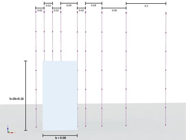
Determine the maximum deformation of a wall divided into two equal parts. The upper and lower parts are made of an elasto-plastic and an elastic material, respectively, and both end planes are restricted to move in the vertical direction. The wall's self-weight is neglected; its edges are loaded with horizontal pressure ph, and the middle plane by vertical pressure.
A planar truss consisting of four sloped members and one vertical member is loaded at the upper node by means of a vertical force and an out-of-plane force. Assuming the large deformation analysis and neglecting the self-weight, determine the normal forces of the members and the out-of-plane displacement of the upper node.
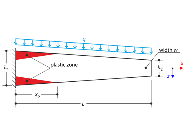
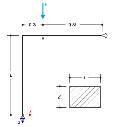
A tapered cantilever is fully fixed on the left end and subjected to a continuous load q. Small deformations are considered and the self-weight is neglected in this example. Determine the maximum deflection.
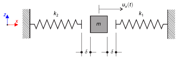
A single-mass system with clearance and two springs is initially deflected. Determine the natural oscillations of the system - deflection, velocity, and acceleration time course.
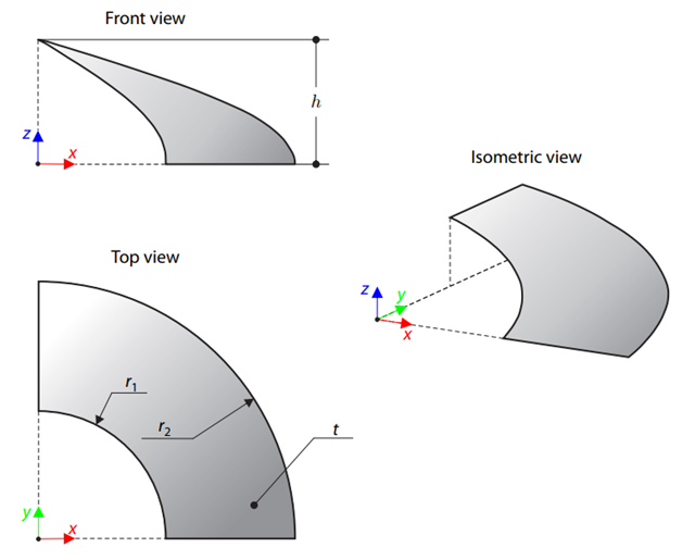
A membrane is stretched by means of isotropic prestress between two radii of two concentric cylinders not lying in a plane parallel to the vertical axis. Find the final minimum shape of the membrane - the helicoid - and determine the surface area of the resulting membrane. The add-on module RF-FORM-FINDING is used for this purpose. Elastic deformations are neglected both in RF-FORM-FINDING and in the analytical solution; self-weight is also neglected in this example.
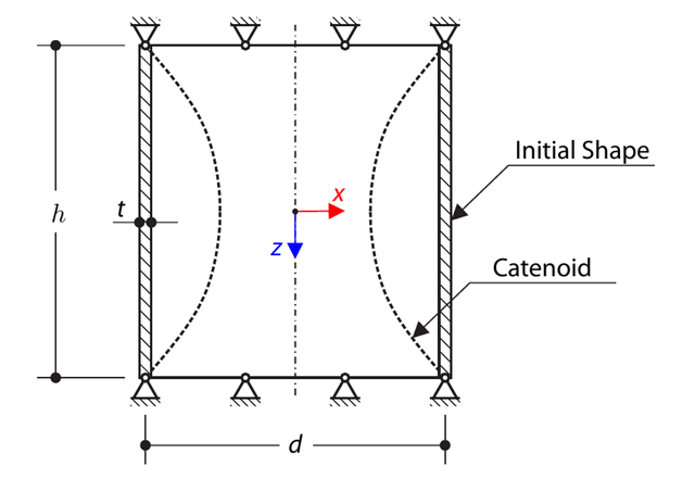
A cylindrical membrane is stretched by means of isotropic prestress. Find the final minimal shape of the membrane - catenoid. Determine the maximum radial deflection of the membrane. The add-on module RF-FORM-FINDING is used for this purpose. Elastic deformations are neglected both in RF-FORM-FINDING and in the analytical solution; self-weight is also neglected in this example.
A symmetrical shallow structure is made of eight equal truss members, which are embedded into hinge supports. The structure is loaded by a concentrated force and alternatively by imposed nodal deformation over the critical limit point when the snap-through occurs. Imposed nodal deformation is used in RFEM 5 and RSTAB 8 to obtain the full equilibrium path of the snap-through. The self-weight is neglected in this example. Determine the relationship between the actual loading force and the deflection, considering large deformation analysis. Evaluate the load factor at the given deflections.
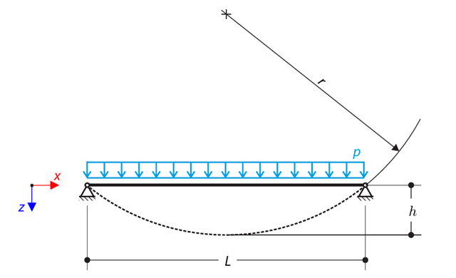
A cable is loaded by means of a uniform load. This causes the deformed shape in the form of the circular segment. Determine the equilibrium force of the cable to obtain the given sag of the cable. The add-on module RF-FORM-FINDING is used for this purpose. Elastic deformations are neglected both in RF-FORM-FINDING and in the analytical solution; self-weight is also neglected in this example.
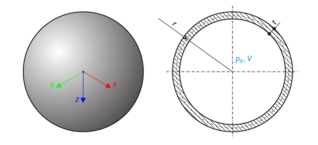
A spherical balloon membrane is filled with gas with atmospheric pressure and defined volume (these values are used for FE model definition only). Determine the overpressure inside the balloon due to the given isotropic membrane prestress. The add-on module RF-FORM-FINDING is used for this purpose. Elastic deformations are neglected both in RF-FORM-FINDING and in the analytical solution; self-weight is also neglected in this example.
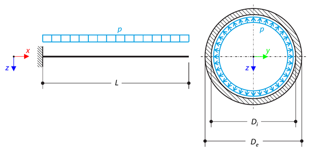
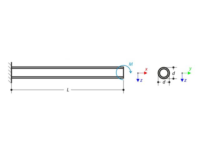
A pipe with a tubular cross-section is loaded by internal pressure. This internal pressure causes axial deformation of the pipe (the Bourdon effect). Determine the axial deformation of the pipe endpoint.
A structure is made of four truss members, which are embedded into hinge supports. The structure is loaded by a concentrated force and alternatively by imposed nodal deformation over the critical limit point, when snap-through occurs. Imposed nodal deformation is used in RFEM 5 and RSTAB 8 to obtain the full equilibrium path of the snap-through. The self-weight is neglected in this example. Determine the relationship between the actual loading force and the deflection, considering large deformation analysis. Evaluate the load factor at given deflections.
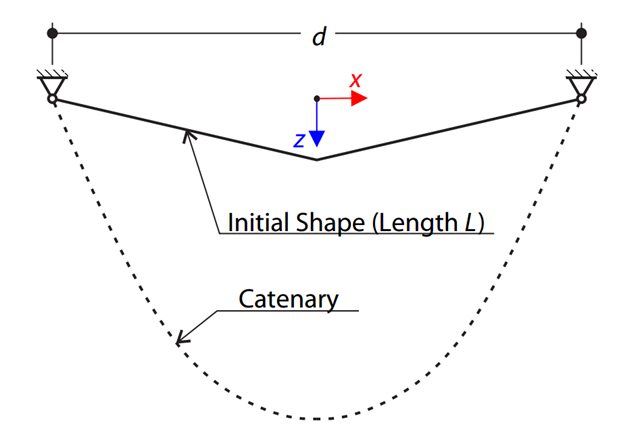
A very stiff cable is suspended between two supports. Determine the equilibrium shape of the cable (the catenary), consider the gravitational acceleration, and neglect the stiffness of the cable. Verify the position of the cable at the given test points.
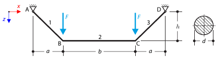
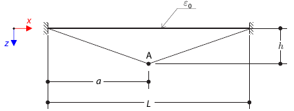
A cable in the initial position is loaded by two concentrated forces. The self‑weight is neglected. Determine the normal forces in the cable.
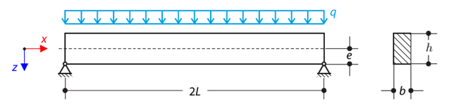
A pinned beam with a rectangular cross‑section is subjected to distributed loading and shifted vertically by eccentricity. Considering the small deformation theory, neglecting the self‑weight, and assuming that the beam is made of isotropic elastic material, determine the maximum deflection.
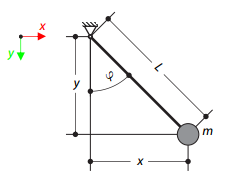
The mathematical pendulum consists of a zero‑weight rope and a mass point at its end. The pendulum is initially deflected. Determine the angle of the rope at the given test time.
A thin string is tensioned by initial strain and initially deflected. Determine the deflection of the test point at the given test times.
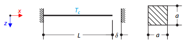
A steel rod between two rigid supports with a gap is loaded by a temperature difference. While neglecting self‑weight, determine the total deformation of the rod and its internal axial force.
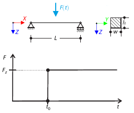
A concentrated force is suddenly applied at the mid‑span of a simply supported beam at a given time. Considering only the small deformation theory, determine the maximum deflection of the beam.