
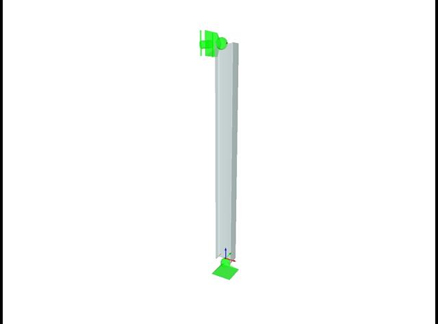
A structure is consisted of the I-profile beam and two tube trusses. The structure is containing several imperfections and it is loaded by the force Fz. The self-weight is neglected in this example. Determine the deflections uy and uz and axial rotation φx at the endpoint (point 4). The verification example is based on the example introduced by Gensichen and Lumpe.
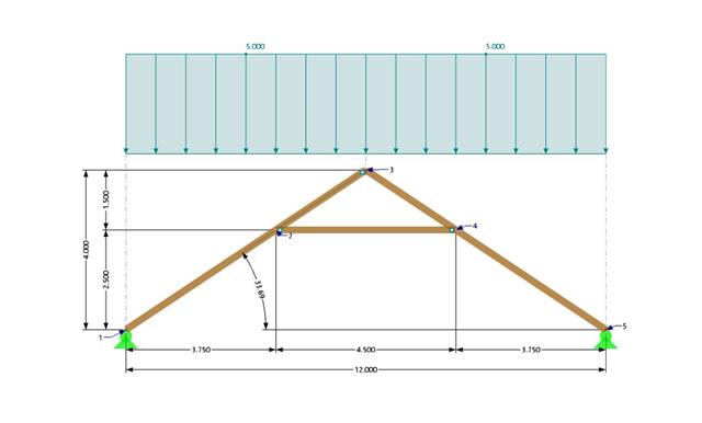
A collar beam roof with the selected geometry is compared in terms of its internal forces between the calculation using RFEM 6 and the manual calculation. In total, three load systems are analyzed.

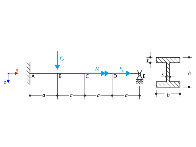
Continuous beam with four spans is loaded by axial and bending forces (replacing imperfections). All supports are fork - warping is free. Determine displacements uy and uz, moments My, Mz, Mω and MTpri and rotation φx. The verification example is based on the example introduced by Gensichen and Lumpe.

In this example, the shear at the interface between concrete cast at different times and the corresponding reinforcement are determined according to DIN EN 1992-1-1. The obtained results with RFEM 6 will be compared to the hand calculation below.

A reinforced concrete beam is designed as a two-span beam with a cantilever. The cross-section varies along the length of the cantilever (tapered cross-section). The internal forces, the required longitudinal and shear reinforcement for the ultimate limit state are calculated.

In this verification example, the capacity design values of shear forces on beams are calculated in accordance with EN 1998-1, 5.4.2.2 and 5.5.2.1 as well as the capacity design values of columns in flexure in accordance with 5.2.3.3(2). The system consists of a two span reinforced concrete beam with a span length of 5.50m. The beam is part of a frame system. The results obtained are compared with those in [1].
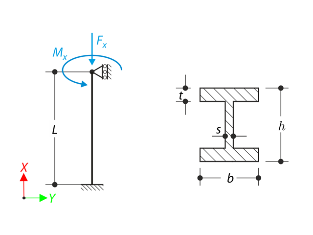
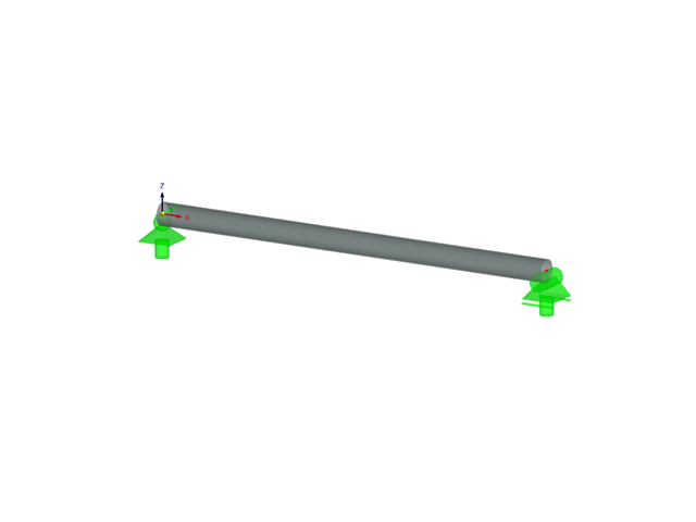
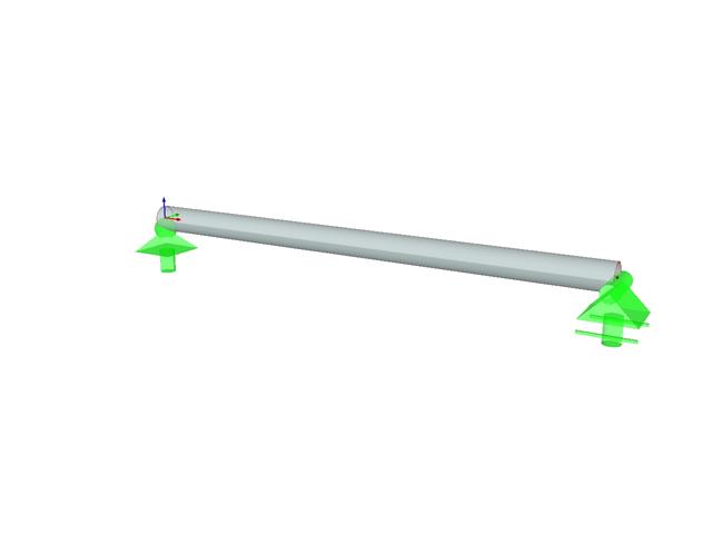
A member with the given boundary conditions is loaded by torsional moment and axial force. Neglecting its self-weight, determine the beam's maximum torsional deformation as well as its inner torsional moment, defined as the sum of a primary torsional moment and torsional moment caused by the normal force. Provide a comparison of those values while assuming or neglecting the influence of the normal force. The verification example is based on the example introduced by Gensichen and Lumpe.
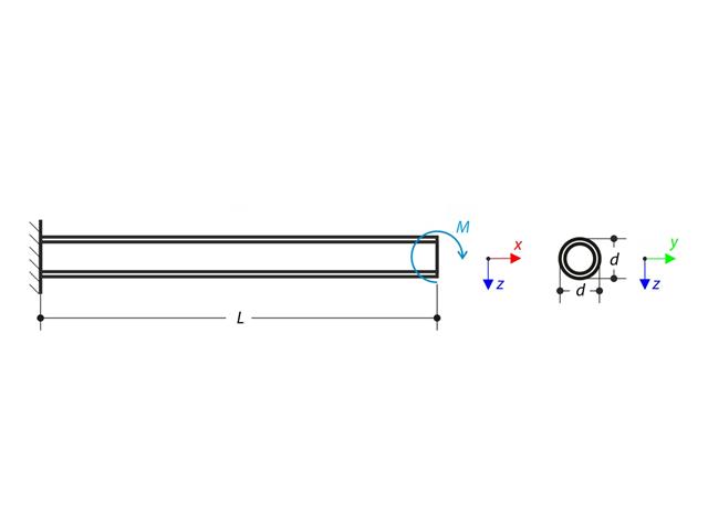
A cantilever is loaded by a moment at its free end. Using the geometrically linear analysis and large deformation analysis, and neglecting the beam's self-weight, determine the maximum deflections at the free end. The verification example is based on the example introduced by Gensichen and Lumpe.

An inner column in the first floor of a three-story building is designed. The column is monolithic connected with the top and bottom beams. The fire design simplified method A for columns according to EC2-1-2 is than proofed and the results compared to [1].
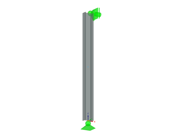
A beam is fully fixed (warping is restricted) on the left end and supported by a fork support (free warping) on the right end. The beam is subjected to a torque, longitudinal force, and transverse force. Determine the behavior of the primary torsional moment, secondary torsional moment and warping moment. The verification example is based on the example introduced by Gensichen and Lumpe (see reference).
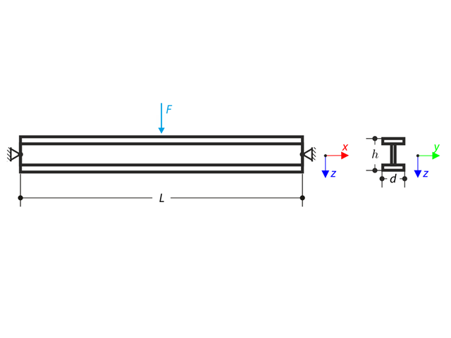
Beam pinned at the both ends is loaded by means the transversal force at the middle. Neglecting its self-weight and shear stiffness, determine the maximum deflection, normal force and moment at the mid-span assuming the second and the third order theory. The verification example is based on the example introduced by Gensichen and Lumpe (see the reference).
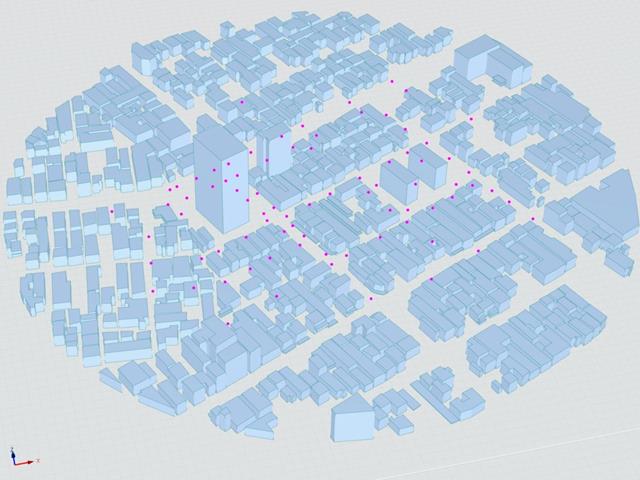
The Architectural Institute of Japan (AIJ) has presented a number of well-known benchmark scenarios of wind simulation.
The following article deals with "Case E - Building Complex in Actual Urban Area with Dense Concentration of Low-Rise Buildings in Niigata City".
In the following, the described scenario is simulated in RWIND& 2 and the results are compared with the simulated and experimental results by AIJ.
Das Architectural Institute of Japan (AIJ) hat eine Reihe an bekannten Benchmark-Szenarien für Windsimulation vorgestellt.
Der Nachfolgende Beitrag dreht sich dabei um den "Case A - high-rise building with a 2:1:1 shape".
Im Folgenden wird das beschriebene Szenario in RWIND2 nachgebildet und die Ergebnisse mit den simulierten und der experimentellen Resultate des AIJ verglichen.
The Architectural Institute of Japan (AIJ) has presented a number of well-known benchmark scenarios of wind simulation.
The following article deals with "Case D - High-Rise Building Among City Blocks".
In the following, the described scenario is simulated in RWIND 2 and the results are compared with the simulated and experimental results by the AIJ.
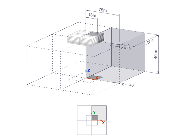
The settlements of a rigid square foundation on a lacustrine clay [1] are calculated with RFEM. One quarter of the foundation is modelled. The foundation has a width of 75.0 m in both sides. Construction stages are used to generate the results.

Consider an ASTM A992 W 18x50 beam forspan and uniform dead and live loads as shown in Figure 1. The member is limited to a maximum nominal depth of 18 inches. The live load deflection is limited to L/360. The beam is simply supported and continuously braced. Verify the available flexural strength of the selected beam, based on LRFD and ASD.
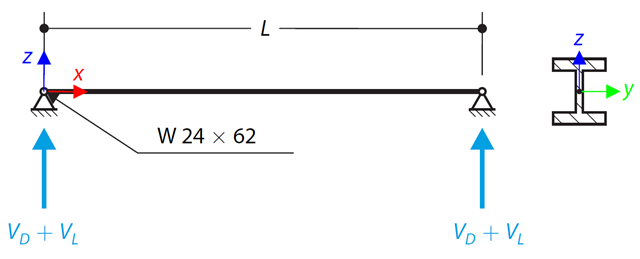
An ASTM A992 W 24×62 beam with end shears of 48.000 and 145.000 kips from the dead and live loads, respectively, is shown in Figure 1. Verify the available shear strength of the selected beam, based on LRFD and ASD.

Using AISC Manual tables, determine the available compressive and flexural strengths and whether the ASTM A992 W14x99 beam has sufficient available strength to support the axial forces and moments shown in Figure 1, obtained from a second-order analysis that includes P-𝛿 effects.
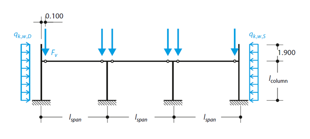
A reinforced concrete column is designed for ULS at normal temperature according to DIN EN 1992-1-1/NA/A1:2015, based on 1990-1-1/NA/A1:2012-08. The design employs the nominal curvature method; see DIN EN 1992-1-1, Section 5.8.8. The addressed column is located at the edge of a 3-span frame structure, which consists of 4 cantilever columns and 3 individual trusses hinged to them. The column is subjected to the vertical force of the precast truss, snow and wind. The results are compared with the literature.
Verify that a beam of different cross-sections made of Alloy 6061-T6 is adequate for the required load, in accordance with the 2020 Aluminum Design Manual.
Determine the allowable axial compressive strength of a pinned 8-foot-long beam of various cross-sections made of Alloy 6061-T6 and laterally restrained to prevent buckling about its weak axis in accordance with the 2020 Aluminum Design Manual.
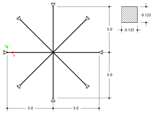
Determine the first sixteen natural frequencies of a double cross with a square cross-section. Each of the eight arms is modeled by means of four beam elements and has a pin support at the end (the x- and y-deflections are restricted). The vibrations are considered only in plane xy. The problem is defined according to The Standard NAFEMS Benchmarks.
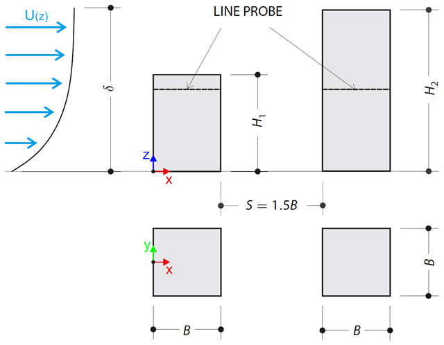
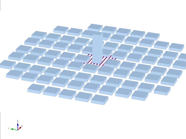
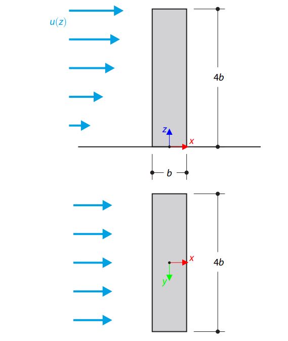
The verification example describes pressure loads on the walls of buildings in tandem arrangement located at ground level. The buildings are simplified to rectangular objects and scaled down while maintaining the elevation ratios. The pressure distribution on the walls of the model of a medium-high building was conducted by an experiment. The chosen results (pressure coefficient Cp) are compared with the measured values.
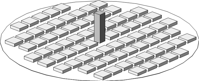
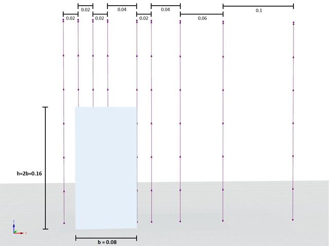
The verification example describes the steady-state flow around a high-rise building in city blocks (scaled model). The example is given by the Architectural Institute of Japan (AIJ). The chosen results (velocity magnitude) are compared with the measured values.
The verification example describes the steady-state flow around an isolated building (scaled model).The example is given by the Architectural Institute of Japan (AIJ). The chosen results (velocity magnitude) are compared with the measured values.
Determine the allowable axial compressive strength of a pinned 8-foot-long beam of various cross-sections made of Alloy 6061-T6 and laterally restrained to prevent buckling about its weak axis in accordance with the 2020 Aluminum Design Manual.
Verify that a beam of different cross-sections made of Alloy 6061-T6 is adequate for the required load, in accordance with the 2020 Aluminum Design Manual.
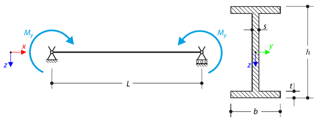
A simply supported beam is loaded by pure bending. Determine the critical load and corresponding load factor due to lateral buckling.
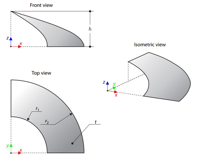
A membrane is stretched by means of isotropic prestress between two radii of two concentric cylinders not lying in a plane parallel to the vertical axis. Find the final minimum shape of the membrane - the helicoid - and determine the surface area of the resulting membrane. The add-on module RF-FORM-FINDING is used for this purpose. Elastic deformations are neglected both in RF-FORM-FINDING and in the analytical solution; self-weight is also neglected in this example.
Determine the allowable axial compressive strength of a pinned 8-foot-long beam of various cross-sections made of Alloy 6061-T6 and laterally restrained to prevent buckling about its weak axis in accordance with the 2015 Aluminum Design Manual.