Kauffman Center for the Performing Arts, Kansas City, Missouri, USA
Customer Project
The Kauffman Center for the Performing Arts located in Kansas City, MO has a floor space of 286,000 ft2. The glass atrium is the signature feature of this building (dimensions L x W x H: 317 ft x 73 ft x 70 ft) which connects the main entry to both performance venues.
Architect |
Safdie Architects, USA www.msafdie.com |
General Contractor |
JE Dunn Construction Co., USA www.jedunn.com |
Planning, Structural Analysis & Atrium Construction |
Novum Structures LLC, USA www.novumstructures.com |
Model
The glass facade and the glass skylight are supported entirely by the cable structure. This design was conceived as a cello’s strings fanning over a bridge and fret-board.
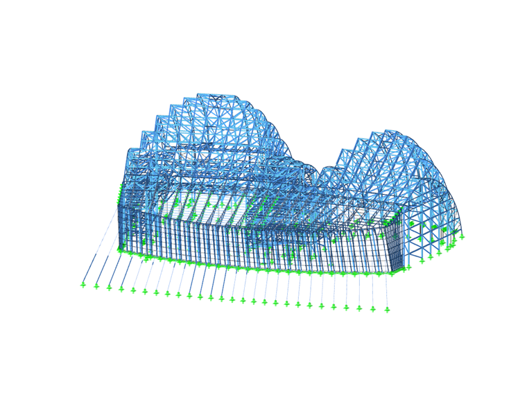
The structural analysis of the atrium steel‑glass structure was performed using RSTAB by the Dlubal customer Novum Structures. In addition, Novum was responsible for engineering, fabricating and constructing the project.
Structure
The two massive steel constructions that house the theatres (Muriel Kauffman Theatre and Helzberg Hall) hold the upper end of a series of parallel cable trusses. The low end of the cables are anchored externally in the second floor slab after crossing pipe columns that define the line of the glazed walls and act as cable stays. In addition, they form the primary roof and perimeter frame structure. Lightweight steel purlins, spanning between adjacent roof cable trusses, support the skylight glass units which are secured with Novum’s Edge Clamp Glass System. A secondary cable system of vertical and inclined cables supports the glass wall units and are secured with Novum’s Corner Clamped Glass System.
The atrium contains 48,300 ft² of insulating, laminated glass that is comprised of 1,147 irregularly shaped segments, each weighing 600 to 800 lbs. The primary rectangular glass panels on the roof are 2 1/16 in thick. The wall panels are 1 3/4 in thick.
Project Location
Write Comment...
Write Comment...
Contact us
Do you have questions or need advice?
Contact our free e-mail, chat, or forum support or find various suggested solutions and useful tips on our FAQ page.
Recommended Events
Videos
Models to Download
Knowledge Base Articles

New
Design of a welded truss
This technical article deals with the component and cross-section designs of a welded truss in the ultimate limit state. Furthermore, the deformation analysis in the serviceability limit state is described.
Screenshots
Product Features Articles

Material Database with Steels According to the Australian Standard AS/NZS 4600:2005
The material database in RFEM, RSTAB and SHAPE-THIN contains steels according to the Australian standard AS/NZS 4600:2005.Frequently Asked Questions (FAQ)
- In the RF‑/STEEL EC3 add-on module, I obtain an extremely high design ratio for a member in the case of "Biaxial bending, shear and axial force." Although the axial force is relatively high, the design ratio seems to be unrealistic. What is the reason?
- For which programs is the STEEL Warping Torsion add-on module available?
- I have just noticed that the STEEL EC3 add-on module also calculates with γM0 = 1.0 when designing a tension member, although it should actually be γM2 = 1.25. How can I perform the design correctly?
- Is it possible to design intermittent welds in the CRANEWAY add-on module?
- I design a cross-section created in the SHAPE‑THIN program by using the RF‑STEEL EC3 add-on module, but the program shows the error message "ER006 Invalid type of c/t-part for cross-section of type General." What can I do?
- For a buckling analysis, FE‑BUCKLING determines the governing shear stress of τ = 7.45 kN/cm², while RF‑/STEEL gives the result of the maximum shear stress of τ = 8.20 kN/cm². Where does this difference come from?
- Why do I get a design ratio for the stability analysis according to 6.2.9.1 in the STEEL EC3 add-on module? Why is a * added to Equation (6.36)?
- I design a frame with a taper (docked cross-section). STEEL EC3 classifies the taper in Cross-Section Class 3. Accordingly, the elastic resistances are taken into account, which is very unfavorable. According to the standard, the taper should be categorized in Class 1, and thus the plastic reserve should also be usable.
- When modeling a beam connection to a continuous column, I have the problem that the column flange fails under bending. If I add backing plates in the FRAME‑JOINT Pro add-on module, nothing changes for all design ratios. Why?
- I would expect the results from my load combination (CO) set to a linear analysis to equal the summation of the results from my load cases (LC) also set to a linear analysis. Why do the results not match?