


Thin-walled timber pipes have a low dead load and good dynamic properties. This improves the material efficiency and vibration behavior, as well as increasing the resistance to material fatigue.
The Technical University of Dresden was responsible for the design and dimensioning of the lattice tower. RSTAB structural frame and truss analysis software was used for the design.
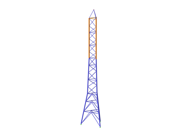
Structure
The lattice tower has a total height of 32 m (104 ft) and carries the wind power plant with an output of 10 kW (1.34 hp). The lowest approximately 18.5 M (60.70 ft) of the structure consists of S235 steel pipes. The truss segment with a length of about 11 m (36 ft) with molded timber pipes d = 240 mm (9.45 in) and steel pipe diagonals was placed on top.
The molded timber pipes consist of pre-compressed timber panels that have been bent into thin-walled tubular cross-sections under the action of heat and steam. The Institute of Steel and Timber Construction developed this molded timber method. Structural components produced in this way have a very high load-bearing capacity with a very low dead load. A thin layer of fiber-reinforced plastics was also applied on the outside. This increases the compressive strength by up to 50% and provides the structure with protection against weathering.
The longitudinal joints of the timber columns consist of steel pipes to which the diagonals also connect. A special feature of these connections is that they were glued. Before they were used, they were extensively analyzed experimentally and numerically by TU Dresden. The analyses resulted in limit strengths for the connections that could be taken into account in the RSTAB calculation.
After the construction of the lattice tower, all the steel parts and transitions to the timber pipes were given an anticorrosive coating. The research project showed that molded timber pipes are very suitable as load-bearing components in tower structures subjected to vibration. The greatest advantage is the lower dead load compared to steel, and thus the reduction of the vibrating mass. In this project, the dead load of the uppermost segment could be reduced by 1.2 tons (1.32 US tons) compared to steel. In addition, the damping material properties of the timber reduced the effects of fatigue on the lower structural components.
This research project was funded by the Central Innovation Programme for Small and Medium-Sized Enterprises (ZIM) of the German Federal Ministry for Economic Affairs and Energy (BMWi).
Literature
Hahn, B., Werner, T.-E., & Haller, P. (2021). BAUINGENIEUR BD.96, No.01-02, pp. 11-18.
| Location | Cossener Straße 2 09328 Lunzenau Germany |
| Research Project Sponsor | Zukunftsinitiative Mittelstand (ZIM) |
| Design, Structural Analysis, Construction | TU Dresden – Institute for Structural Analysis and Dynamics |
| Construction and Assembly | STM Montage GmbH |


