


.png?mw=1000&hash=6367fcf778723db4ccdf933022948f1d36d9bacb)


.png?mw=200&hash=600fb0ad6014d7cae3c5137748acfdc861999c47)


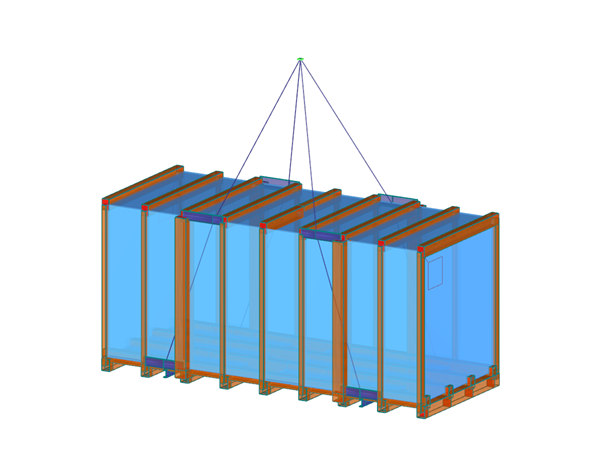


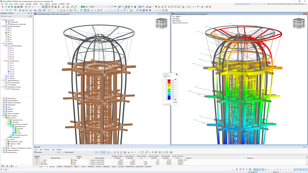
Customer A2 Timber s.r.o. used RFEM and RWIND to design the first timber building without a metal structure of its kind in Japan. The 12-meter-high spiral pavilion, made of prefabricated CLT panels and glass facade elements, was analyzed for wind and seismic loads using a digital wind tunnel and FEM modeling.
- Osaka, Japan


.png?mw=200&hash=ceabdac71454991b172d1a40faa3844b9a756ff1)


