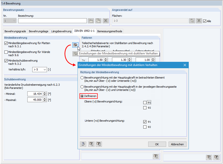
According to EN 1992‑1‑1, Clause 9.3.1, the minimum reinforcement for ensuring ductile behavior of the structural component is to be placed in the main span direction of the plate. In RF‑CONCRETE Surfaces, the "Reinforcement direction with the main tension force in the considered element" option is selected by default. This means that for each element, the program searches for the greatest tension force for each reinforcement direction and for the top surface (-z) and the bottom surface (+z). If the greatest tension force has been found for the individual element, the minimum reinforcement is applied there. If you want to arrange the minimum reinforcement in the principal stress direction for biaxially stressed slabs only, you can specifically control this. To do this, open the "Settings of Min. Reinforcement for Ductile Properties" dialog box. If you select "Define", you can specifically set in which direction and on which side of the structural component the minimum reinforcement should be arranged.
Question
For the design of biaxially stressed slabs in RF‑CONCRETE Surfaces, I obtain minimum reinforcement in both slab directions. Is it possible to set in the add-on module where the minimum reinforcement should be applied?
Answer:
Do you have any questions?
This article deals with rectilinear elements of which the cross-section is subjected to axial compressive force. The purpose of this article is to show how very many parameters defined in the Eurocodes for concrete column calculation are considered in the RFEM structural analysis software.
RF-CONCRETE Members also includes the design of a shear joint. In order to perform this design, you should select the "Shear joint available" check box in Window 1.6, Shear Joint tab.
It is possible to edit a reinforcement layout or an existing reinforcement directly in the reinforcement's 3D rendering.
The reinforced concrete design for fire situations is carried out according to the simplified method based on EN 1992-1-2, Clause 4.2. The "zone method" described in Annex B.2 is used: The cross-section is subdivided into a number of parallel zones of equal thickness, and their temperature-dependent compressive strength is determined. The reduced load-bearing capacity in the event of fire exposure is thus represented by a reduced structural component's cross-section with reduced strengths.
The reinforcement proposal from RF-/CONCRETE Members can be exported to Revit. The rectangular and circular cross-sections are currently supported.
The reinforcement bars can be modified retroactively in Revit.
Surface reinforcements defined in the RF-CONCRETE Surfaces add-on module can be exported to Revit as reinforcement objects via the direct interface. To do this, you can optionally select surface, rectangular, polygon, and circular reinforcement areas in RF-CONCRETE Surfaces. In addition to bar reinforcement, it is possible to export mesh reinforcement.
- Automatic import of internal forces from RFEM
- Ultimate limit state and serviceability limit state design
- The module extension EC2 for RFEM enables the design of reinforced concrete members according to EN 1992‑1‑1:2004 (Eurocode 2) and the following National Annexes:
- DIN EN 1992-1-1/NA/A1:2015-12 (Germany)
- ÖNORM B 1992-1-1:2018-01 (Austria)
- NBN EN 1992-1-1 ANB:2010 (Belgium)
- BDS EN 1992-1-1:2005/NA:2011 (Bulgaria)
- EN 1992-1-1 DK NA:2013 (Denmark)
- NF EN 1992-1-1/NA:2016-03 (France)
- SFS EN 1992-1-1/NA:2007-10 (Finland)
- UNI EN 1992-1-1/NA:2007-07 (Italy)
- LVS EN 1992-1-1:2005/NA:2014 (Latvia)
- LST EN 1992-1-1:2005/NA:2011 (Lithuania)
- MS EN 1992-1-1:2010 (Malaysia)
- NEN-EN 1992-1-1+C2:2011/NB:2016 (Netherlands)
- NS EN 1992-1 -1:2004-NA:2008 (Norway)
- PN EN 1992-1-1/NA:2010 (Poland)
- NP EN 1992-1-1/NA:2010-02 (Portugal)
- SR EN 1992-1-1:2004/NA:2008 (Romania)
- SS EN 1992-1-1/NA:2008 (Sweden)
- SS EN 1992-1-1/NA:2008-06 (Singapore)
- STN EN 1992-1-1/NA:2008-06 (Slovakia)
- SIST EN 1992-1-1:2005/A101:2006 (Slovenia)
- UNE EN 1992-1-1/NA:2013 (Spain)
- CSN EN 1992-1-1/NA:2016-05 (Czech Republic)
- BS EN 1992-1-1:2004/NA:2005 (United Kingdom)
- TKP EN 1992-1-1:2009 (Belarus)
- CYS EN 1992-1-1:2004/NA:2009 (Cyprus)
- In addition to the National Annexes (NA) listed above, you can also define a specific NA, applying user‑defined limit values and parameters.
- Flexibility due to detailed setting options for basis and extent of calculations
- Fast and clear results output for an immediate overview of the result distribution after the design
- Graphical results output integrated in RFEM; for example, required reinforcement
- Numerical results clearly arranged in tables and graphical display of the results in the model
- Complete integration of results in the RFEM printout report
- Free definition of two or three reinforcement layers in the ultimate limit state
- Vectorial representation of the main stress directions of internal forces allowing optimal orientation adjustment of the third reinforcement layer to the actions
- Design alternatives to avoid compression or shear reinforcement
- Design of surfaces as deep beams (theory of membranes)
- Option to define basic reinforcements for top and bottom reinforcement layers
- Definition of designed reinforcement for serviceability limit state design
- Result output in points of any selected grid
- Optional extension of the module with nonlinear deformation analysis. The calculation is performed in RF‑CONCRETE Deflect by reducing the stiffness according to the standard, or in RF‑CONCRETE NL by the general nonlinear calculation determining the stiffness reduction in an iterative process.
- Design with design moments at column edges
- Precise breakdown of reasons for failed design
- Design details of all design locations for better traceability of reinforcement determination
- Export of isolines for the longitudinal reinforcement in a DXF file for further use in CAD programs as a basis for reinforcement drawings