The total rotational spring comprises several individual rotational springs, which are given in [1] as Equation 10.11.
In the case of a non-continuous rotational restraint by purlins, RF-/STEEL EC3 takes into account the rotational stiffness due to the connection stiffness CD,A, the rotational stiffness CD,C due to the bending stiffness of the available purlins, and also the rotational stiffness CD,B due to the section deformation, if activated.
Since the execution of the connection is unknown, the infinite value is set by default. The spring stiffnesses are considered as a reciprocal value 1/C, thus giving "infinitely" the result of spring stiffness = 0. If you know the rotational spring stiffness of the connection, you can specify this value manually.
The rotational restraint CD,C is determined from the bending stiffness according to the following formula:
|
E |
E-Modul |
|
k |
Beiwert für Lage (Innenfeld, Außenfeld) |
|
I |
Trägheitsmoment Iy |
|
s |
Abstand der Riegel |
|
e |
Abstand der Pfetten |
The rotational stiffness CD,B due to the bending stiffness is determined according to the following formula; see [3] and [4]:
|
E |
E-Modul |
|
tw |
Stegdicke Binder bzw. gestütztes Bauteil |
|
G |
G-Modul |
|
h |
Höhe des Binders bzw. gestütztes Bauteil |
|
tf |
Flanschdicke des Binders |
|
b |
Breite Binder |
|
e |
Abstand der Pfetten |
The attached example includes two design cases.
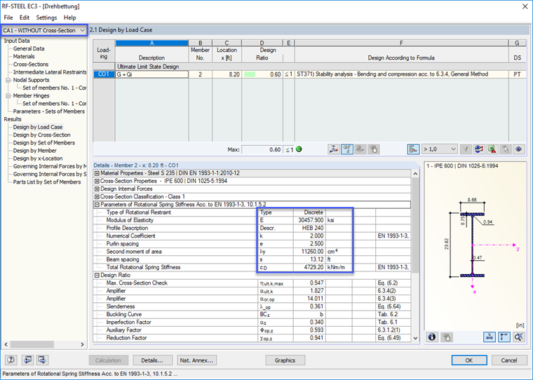
Case 1 was designed without taking into account the cross-section deformation. The total rotational spring stiffness is
CD = CD,C = 4,729 kNm/m
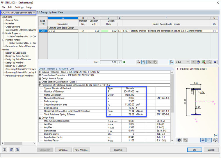
Case 2 was designed while taking into account the cross-section deformation. The total rotational spring stiffness is
CD = 72.02 kNm/m
Single spring CD,B = 73.14 kNm/m
Single spring CD,C = 4,729 kNm/m
Total spring: