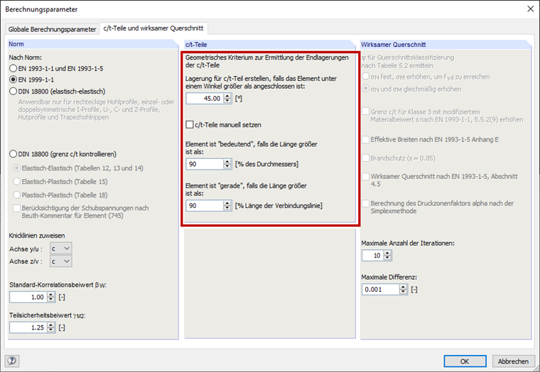
FAQ 003430 EN
7 August 2019
003430
How is the automatic creation of c/t-parts carried out?
Answer
It is also possible to specify an angle from which a support should be created between two elements. In case that the angle for connection of elements is smaller, they are considered as an interconnected c/t-part. Stiffeners (longitudinal ribs, slopes (lips), or bulges, and so on) are not recognized by the program during the automatic generation of the c/t-parts. The c/t-parts have to be adjusted manually. You can make the changes in Table "1.7 Notional Flat Widths | EN 1993‑1‑3" or in the "Edit Notional Flat Width" dialog box.
The check box for Element is "significant" controls whether a curved element is considered as a c/t-part. If the length of the arc is larger than the diameter entered here, it cannot be neglected.
A corresponding error message appears before the calculation.
The option Element ist "straight" refers to curved elements. The arcs are usually excluded from the determination of the effective widths because the standards do not provide clear specifications. A curved element is assumed to be straight if the ratio of the connecting line (start/end node) to the element length is higher than the specified value.
Keywords
Contact us
Did you find your question?
If not, contact us via our free e-mail, chat, or forum support, or send us your question via the online form.
Recommended Events
Eurocode 3 | Steel structures according to DIN EN 1993-1-1
Online Training 6 May 2021 8:30 AM - 12:30 PM CEST
Stability Design in Steel Construction with RFEM and RSTAB
Webinar 1 December 2020 2:00 PM - 2:45 PM CET
Designing Cold-Formed Steel Sections According to Eurocode 3
Webinar 30 April 2020 3:00 PM - 3:45 PM CEST
Membrane Structures with Wind Loads From CFD Wind Simulation
Webinar 24 March 2020 3:00 PM - 4:15 PM CET
Dlubal Webinar: Design of Steel Structures According to EC 3 | Part 2: Stability Analysis, Design
Webinar 1 December 2017
Dlubal Webinar: Design of Steel Structures According to EC 3 | Part 1: Modelling, Loading
Webinar 24 November 2017 3:00 PM - 4:00 PM CET
Videos
Models to Download
Knowledge Base Articles

New
CSA S16:19 Stability Considerations and the New Annex O.2
Structure stability is not a new phenomenon when referring to steel design. The Canadian steel design standard CSA S16 and the most recent 2019 release is no exception.
Screenshots
Product Features Articles

SHAPE-THIN determines the effective cross-sections according to EN 1993-1-3 and EN 1993-1-5 for cold-formed sections. You can optionally check the geometric conditions for the applicability of the standard specified in EN 1993‑1‑3, Section 5.2.
The effects of local plate buckling are considered according to the method of reduced widths and the possible buckling of stiffeners (instability) is considered for stiffened sections according to EN 1993-1-3, Section 5.5.
As an option, you can perform an iterative calculation to optimize the effective cross-section.
You can display the effective cross-sections graphically.
Read more about designing cold-formed sections with SHAPE-THIN and RF-/STEEL Cold-Formed Sections in this technical article: Design of a Thin-Walled, Cold-Formed C-Section According to EN 1993-1-3.
Frequently Asked Questions (FAQ)
- How does the calculation of the moments of inertia differ when the cross-section consists of several unconnected or connected partial cross-sections?
- When determining the effective cross-section properties according to EN 1993‑1‑1, EN 1993‑1‑5, or EN 1999̩1‑1, SHAPE‑THIN displays a warning message saying that the effective widths are only determined for straight elements. What does it mean?
-
Why are my steel members not being designed for stability in RF-STEEL AISC?
- My section is classified as Class 4 and non-designable in RF-/STEEL CSA. However, my manual calculation shows a different class. Why the difference?
- I have defined temperature loads, strain loads, or a precamber. As soon as I modify stiffnesses, the deformations are no longer plausible.
- Can the properties, such as B. the cross -section or the surface thickness as well as the material of a surface of an existing element for a new element?
- I am trying to manually check the deformations from the CRANEWAY add-on module. However, I obtain great deviations. How to explain the differences?
- What should be considered when using a failure of columns under tension in the RF‑/DYNAM Pro – Equivalent Loads add-on module?
- Why is there no stability analysis displayed in the results despite the activation of the stability analysis in RF‑/STEEL EC3?
- How can I model and design a crane runway girder with Dlubal Software?
Customer Projects