286 Results
View Results:
Sort by:
Question
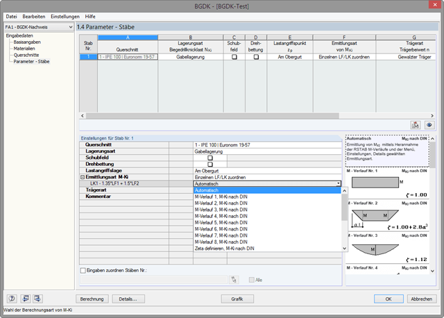
Why are there differences when calculating the elastic critical moment for lateral-torsional buckling Mcr according to DIN 18800 and Eurocode 3?
Question
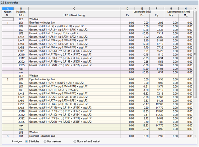
Can I use the displayed support forces directly for a further calculation?

Question
Is it possible to reduce dynamic coefficients when using DIN EN 1993‑6?
Question
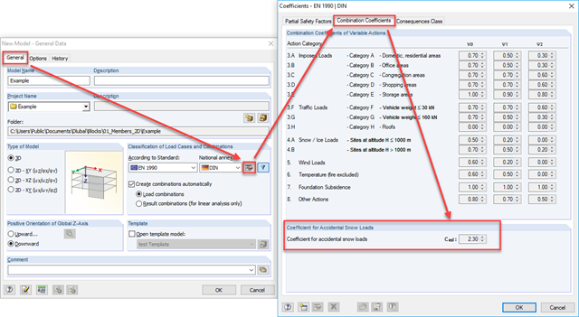
The building I am calculating is located in the North German Plain. How can I consider the increased snow load?
Question
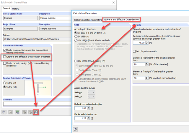
How can I determine the effective cross-section properties according to EC 3 or EC 9 with SHAPE‑THIN?
Question
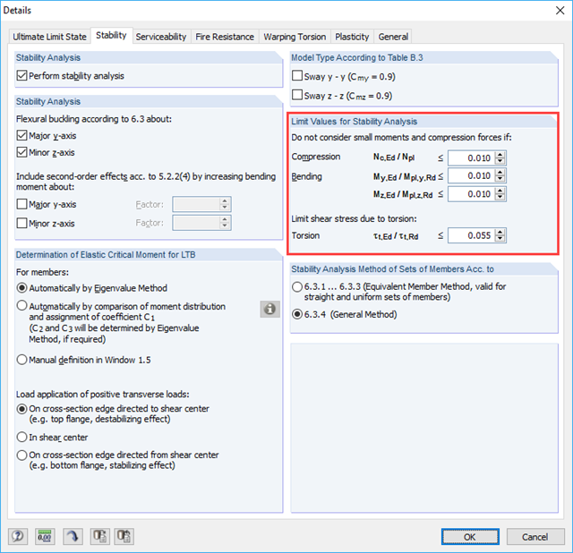
Are there any recommendations or literature and standard references to the "Limit Values for Stability Analysis" settings in Details of RF‑/STEEL EC3?
Question
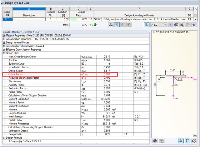
I am performing an analysis according to General Method 6.3.4 EN 1993‑1‑1 and have activated the addition "Adapted Method According to Naumes". The critical factor α*crit is displayed in red. Should I be worried?
Question
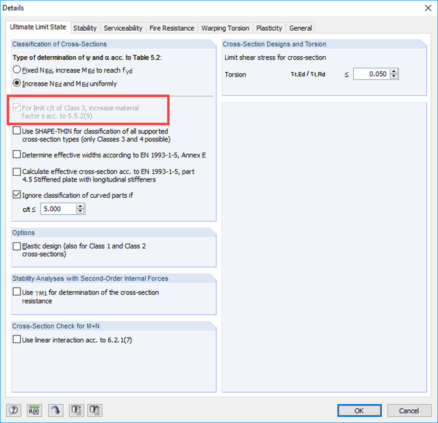
Why is the option to increase the material factor ε grayed out in Details - Ultimate Limit State?
