Differences Between Nodal Support and Intermediate Support
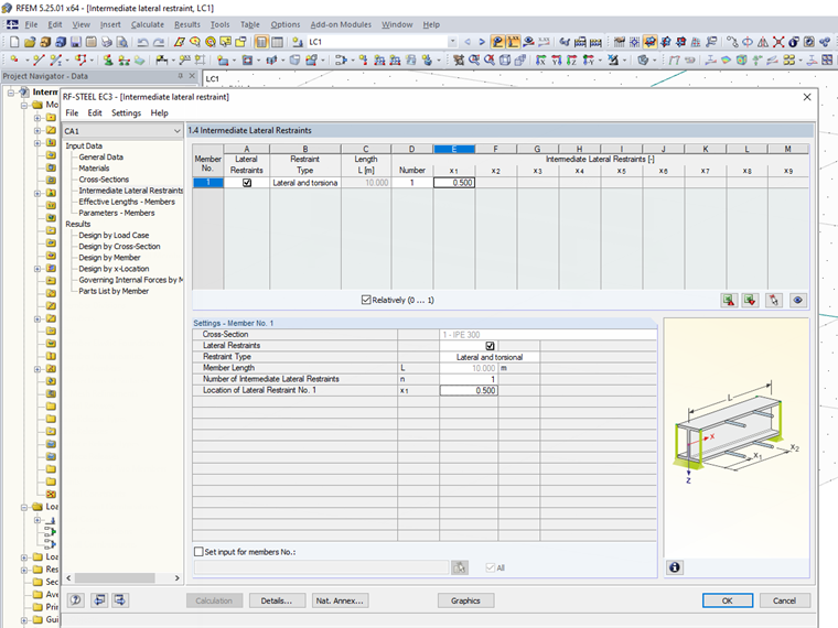
The differences between these two variants can only be found in the input. In general, an intermediate support can only be defined between the start and end points of a member. It is not necessary to divide the member at this point, and you can quickly enter several similar intermediate supports.
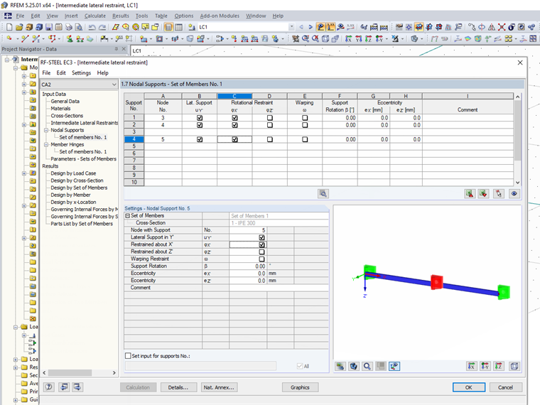
A nodal support is always defined on a node. The member must, therefore, be divided at this point in order to define the support. The effect of an intermediate support in the y-direction and a nodal support with a restraint of uy is identical in the calculation.
However, the nodal support offers more options for user-defined input than the intermediate support, depending on the add-on module. In most of the add-on modules, the intermediate support is applied as a fork support with a restraint of the lateral displacement and a rotation restraint around the longitudinal axis. In the RF‑/STEEL EC3 and RF‑/STEEL AISC add-on modules, however, it is also possible to distinguish between a hinged support on the upper or lower flange, a fork support, or a user-defined lateral support.
Selection of Input Option
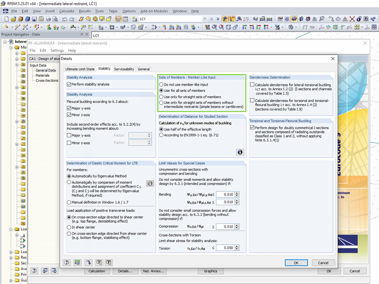
Depending on the design format, a certain input option may be specified. Thus, the nodal supports are not offered in the RF‑/STEEL EC3 add-on module for the equivalent member method, because the boundary conditions are defined by the effective lengths. As a result, it is only possible to use the intermediate support. The nodal supports and the intermediate supports are available for the designs according to the General Method or with RF‑/STEEL Warping Torsion. They are then used depending on whether a node is already defined in the main model or not. Some add-on modules, such as RF‑/ALUMINUM, offer the choice between a member-like input with intermediate supports, or a set of member-like inputs for nodal supports.
Example
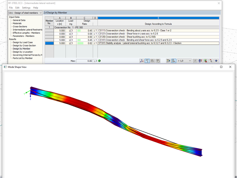
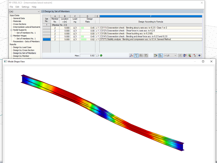
For a single-span beam, the lateral-torsional buckling analysis in RF‑STEEL EC3 is performed with the equivalent member method and an intermediate support in the middle, and compared to a design according to the general method and a central nodal support.
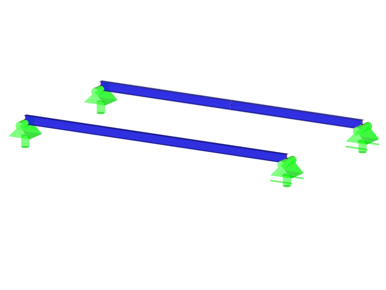
The expected two-wave mode shape results for both input variants.