


Calculation of Warping Spring
If a warping stress is applied, this corresponds to the complete restraint of the cross-section warping, for example via a rigid end plate. In reality, however, this full restraint is usually not given because the end plates are not infinitely rigid, but also deformable. When entering the nodal supports, the design modules for steel and aluminum structures allow for a direct calculation of the warping springs from the variants presented below according to [1].
End Plate
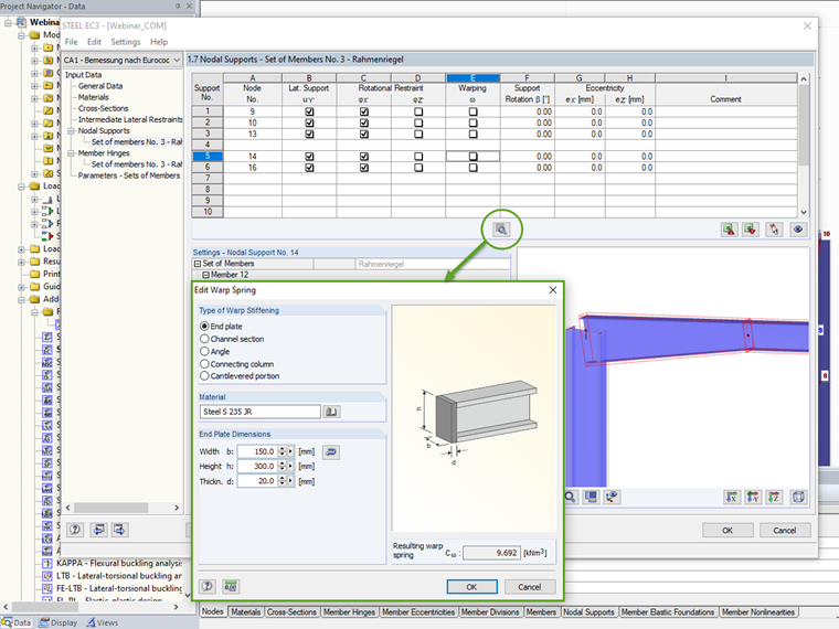
The warping restraint of the end plate results from the torsional stiffness of the connected plate.
|
Cω |
Wölbfeder |
|
G |
Schubmodul |
|
b |
Breite der Stirnplatte |
|
h |
Höhe der Stirnplatte |
|
t |
Dicke der Stirnplatte |
Channel and Angle Sections
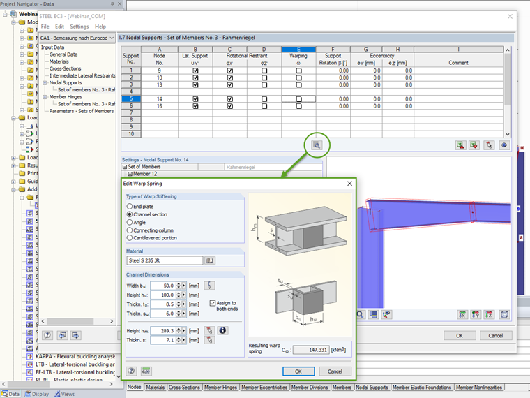

The warping restraint by torsional stiffness transverse bulkheads is significantly greater than by end plates and beam overhang, due to the higher torsional stiffness. U- or L-stiffeners welded on one side together with the web form a box girder; if arranged on both sides, a box girder with larger dimensions results.
|
Cω |
Wölbfeder |
|
G |
Schubmodul |
|
hm |
Abstand der Mittelebenen der Flansche des Trägers |
|
Am |
Von der Mittellinie eingeschlossene Fläche |
|
li |
Seitenlänge |
|
ti |
Blechdicke |
Connecting Column
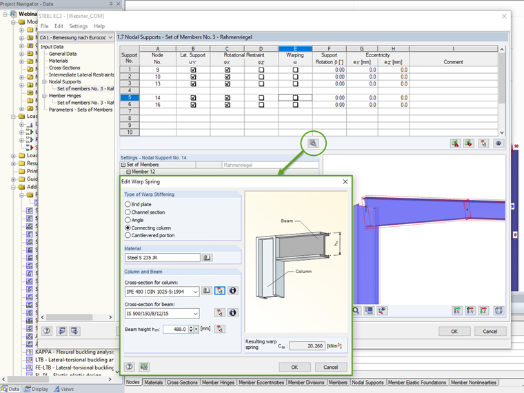
Warping restraint by a connected column results from the torsional stiffness of the column cross-section. The prerequisite for its effectiveness is the arrangement of stiffeners as an extension of the flanges in the column.
|
Cω |
Wölbfeder |
|
G |
Schubmodul |
|
IT |
Torsionsträgheitsmoment |
|
hm |
Abstand der Flanschmittellinien |
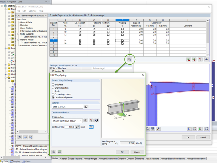
Cantilevered Portion
|
Cω |
Wölbfeder |
|
G |
Schubmodul |
|
IT |
Torsionsträgheitsmoment des überstehenden Trägers |
|
λ |
√[(G ⋅ IT) / (E ⋅ Iω)] |
|
lk |
Überstandslänge |
|
Iω |
Wölbwiderstand des überstehenden Trägers |
