Image 01 shows a round container on the left, and a load that is variable in height is applied on it in a direction normal to the surface. The representation of the free load always refers to a surface resting on a defined plane (XZ-plane in this case) with the normal axis lying in the direction of the free axis (x-axis in this case).
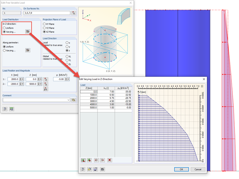
In order to obtain a load variable in height (z‑axis), select the "Varying" option under "In Z‑direction". Then, you can create loads with any elevations using the corresponding button.
The factor kz refers to the value of the constant load, as shown in the image marked in green.
Image 02 shows the same container, but now with a load that is variable in its circumference applied in the surface normal direction. The representation of the free load always refers to a surface resting on a defined plane (XZ-plane in this case), as in the case of the load varying in height. The normal axis rests in the direction of the free axis (the y‑axis, in this case).
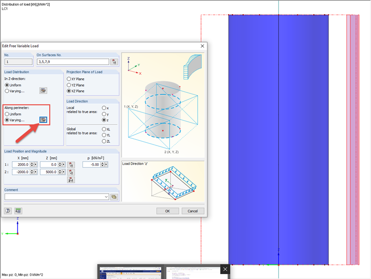
In order to obtain a load varying along the perimeter, select the "Varying" option under "Along perimeter". Then you can use the corresponding button (Image 03) to enter the factors for the load, including the angle under which these factors occur.
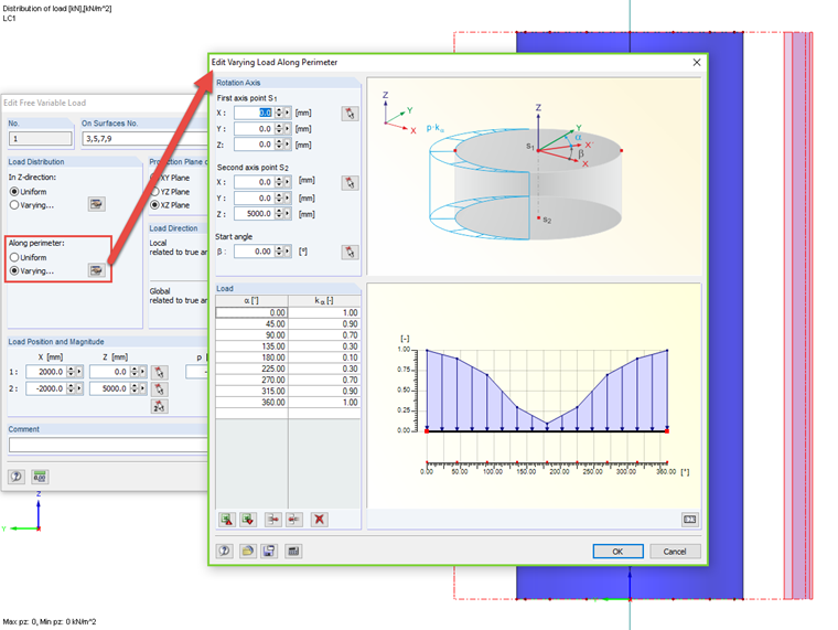
In addition, it is necessary to specify the axis to which the perimeter refers. Also in this case, the factor kα refers to the value of the constant load in the main dialog box (marked in green in the image).
To enter more complex load distributions, you can use the function of exporting and importing for MS Excel as well.