


Structural Modeling
In RFEM 5, the punching shear verification can be carried out both on a 2D slab and on a 3D structure. The RF-STANZ Pro add-on module automatically detects the punching-relevant locations and suggests them for calculation. An integrated filter for finding the punching points can be controlled individually. Thus, a structuring of the verifications, for example by levels, is very easy to achieve.
RF-STANZ Pro automatically recognizes from the structural input in RFEM the type of punching node (single column, wall corner, or wall end) as well as the position of the punching point (interior, edge, or corner column).
Critical Perimeter
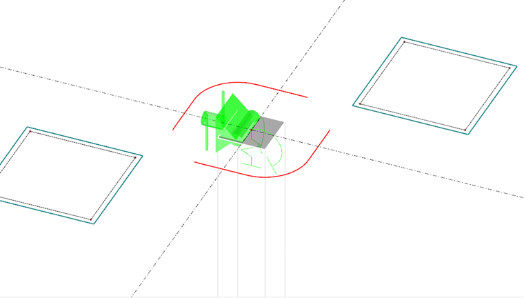
The punching shear verification is to be carried out in the so-called critical perimeter. According to 6.4.2, EC 2 [1], the critical perimeter for slabs is located at a distance of 2 d (d = effective depth of the slab) from the loaded area. To determine the geometry of the critical perimeter, the column dimensions as well as slab openings up to a distance of 6 d from the load introduction area must be taken into account. RF-STANZ Pro automatically recognizes the openings modeled in the FEM calculation. In addition, smaller openings can also be defined in the module (which, for example, are negligible in the static FEM analysis of the slab) and taken into account when determining the geometry of the critical perimeter. The geometry of the critical perimeter is already displayed in the module input screens before the calculation starts.
For foundation slabs or foundations, the critical perimeter is usually located within 2 d from the column edge. According to 6.4.4 (2) [1], an iterative calculation is required to determine the critical perimeter. The German National Annex [2] allows, in the NCI to 6.4.4 (2), a simplified calculation for foundation slabs and slender foundations with λ = aλ / d > 2 (with aλ = foundation projection). In this case, the critical perimeter may be assumed at a distance of 1 d. In RF-STANZ Pro, the iterative solution for determining the critical perimeter is generally performed for foundations/foundation slabs.
Design Shear Force vEd
The design shear force related to the critical perimeter is calculated from Eq. 6.38, EC 2 [1]:
|
β |
Load increase factor for considering an asymmetric shear force distribution in the critical control perimeter |
|
VEd |
Design value of the punching shear load |
|
u1 |
Extent of the critical punching perimeter |
|
d |
effective static effective depth |
To account for the non-rotationally symmetric loading, the punching load VEd is increased by the load increase factor β. For non-sway systems with span differences in the adjacent spans of less than 25%, the following β values may be used according to EN 1992-1-1, Figure 6.21N [1]: β = 1.15 for interior columns β = 1.4 for edge columns β = 1.5 for corner columns The German Annex [2] supplements Figure 6.21N with the β factors for wall corners with β = 1.20 and for wall ends with β = 1.35, and adapts the recommended value for interior columns to β = 1.10.
A generally valid method for determining the load increase factor β is described in Eurocode 2 [1] under Clause 6.4.3 (3). In this case, the factor β is determined assuming a fully plastic shear stress distribution in the critical perimeter. According to EN 1992-1-1 [1], Equation (6.39), one obtains:
|
k |
Coefficient depending on the column dimensions according to EN 1992-1-1, Table 6.1 |
|
MEd |
Moment about the centroidal axis of the critical circular section |
|
VEd |
Design value of the punching load |
|
u1 |
Extent of the critical perimeter cut |
|
W1 |
Section modulus of the critical circular section |

While in Equation (6.39), EN 1992-1-1 [1], the calculation of β is given only for a uniaxial load eccentricity, the German Annex [2] includes the extended Equation (NA.6.39.1) below for accounting for a biaxial load eccentricity:
In RF-STANZ Pro, both of the above-mentioned options for calculating β are available. The model accounting for the fully plastic shear stress distribution is selected as the standard method.
RF-STANZ Pro takes the design value of the shear force VEd directly from the FEM calculation for the punching shear verification. For punching shear verification at columns, nodal supports, and single loads, the design value of the shear force can be determined from the column normal force, reaction force, or load value of the acting concentrated force.
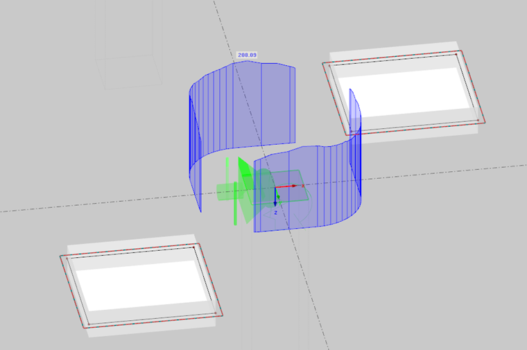
In addition, RF-STANZ Pro offers the possibility of creating the critical perimeter in the FEM model and determining the shear force VEd acting there. The following two options are available:
- The shear forces present in the critical perimeter are integrated or smoothed over the entire critical perimeter. The resulting design shear force VEd must then be multiplied by the load increase factor β (cf. Eq. 6.38 [1]). If the coefficient β is determined using the model of the fully plastic shear stress distribution, then the two bending moments MEd,x and MEd,y are also determined from the integration of the slab internal forces in the created perimeter in the slab.
- Use of the maximum value of the shear forces present in the perimeter for the punching design. With this method, the influence of the non-rotationally symmetric loading is taken into account by using the maximum value. A further increase of the shear force by the factor β is therefore not required.
Although using the maximum value of the shear force in the perimeter is the most accurate method for determining the design value of the punching load, it is also the method most susceptible to singularity effects or, respectively, most at risk. It should be especially noted that when shear forces are taken directly from the perimeter in the FEM calculation, sufficient refinement of the FE mesh in the punching area must be ensured. It is recommended to arrange at least two to three elements between the punching node and the critical perimeter by means of FE mesh refinement.
For foundations and foundation slabs, VEd may be reduced by the soil pressure within the iteratively determined critical perimeter, cf. 6.4.2 (2) [1]. If, according to the German Annex [2], the critical perimeter for slender foundations is simplified to 1 d, only 50% of the soil pressure may be taken into account. Both verification types can be selected in RF-STANZ Pro.
Verification Type
When carrying out the punching shear verification, it is first checked whether the verification can be satisfied without punching reinforcement.
Punching Shear Resistance without Punching Reinforcement
The punching shear resistance without shear reinforcement vRd,c is to be determined according to 6.4.4 (1), EN 1992-1-1 [1], as follows: vRD,c = CRD,c ∙ k ∙ (100 ∙ ρl ∙ fck)1/3 + k1 ∙ σcp ≥ (vmin + k1 ∙ σcp) where CRd,c = 0.18 / γc for flat slabs CRd,c = 0.15 / γc for foundation slabs/foundations k = 1 + √(200 / d) ρl,x/y = Asl,x/y / (bw · dx/y) ρl = √(ρl,x ∙ ρl,y) ≤ 0.02 Asl = area of tensile reinforcement k1 = 0.1 σcp = normal stress in the critical perimeter vmin = 0.035 · k3/2 · fck1/2
In the German Annex [2], the above parameters are modified as follows: CRd,c = 0.18 / γc for flat slabs CRd,c = 0.18 / γc ∙ (0.1 ∙ u0 / d + 0.6) for interior columns of flat slabs with u0 / d < 4 CRd,c = 0.15 / γc for foundation slabs/foundations ρl = √(ρl,x ∙ ρl,y) ≤ min [0.02;0.5fcd/fyd] vmin = (0.00525 / γc) ∙ k3/2 ∙ fck1/2 for d ≤ 600 mm vmin = (0.00375 / γc) · k3/2 · fck1/2 for d > 800 mm
The punching shear verification is satisfied without additional punching reinforcement if vEd ≤ vRd,c. Due to the structurally difficult execution of shear reinforcement, the use of punching reinforcement is usually avoided and the maximum usable longitudinal reinforcement ratio ρl is adopted instead. In RF-STANZ Pro, the required longitudinal reinforcement ratio to avoid punching reinforcement is determined. However, it is also possible to manually define the available longitudinal reinforcement for the calculation of vRd,c.
Maximum Punching Shear Resistance vRd,max
If the verification without punching reinforcement cannot be satisfied, then in the next step the maximum punching shear resistance vRd,max must be verified.
According to 6.4.5 (3) EN 1992-1-1 [1], the maximum punching shear resistance is to be verified at the column face. The length u0 of the face to be considered is to be determined in analogy to the critical perimeter and directly at the load introduction area. The maximum punching shear resistance vRd,max at the column face is to be determined according to 6.4.5(3), EN 1992-1-1 [1], as follows: vRd,max = 0.4 · ν ·fcd where ν = 0.6 · (1 - fck / 250) (fck in [N/mm²])
The acting design shear force at the column face is obtained from: vEd,u0 = β · VEd / (u0 · d)
The verification is satisfied if vEd ,u0 ≤ vRd,max.
The German National Annex [2] does not carry out the verification of the maximum punching shear resistance at the column face but in the critical perimeter u1 with Equation NA6.53.1 as follows: vEd,u1 ≤ vRd,max = 1.4 · vRd,c,u1
Punching Shear Resistance with Punching Reinforcement
If the verification of vRd,max could be successfully carried out, the required punching reinforcement is then determined in the next step. The required punching reinforcement is to be determined by rearranging Equation 6.52 from EN 1992-1-1 [1]. The required reinforcement Asw in one row is therefore obtained as follows:
|
vEd |
Related shear force |
|
VRd,c |
Punching shear resistance without punching shear reinforcement |
|
d |
mean effective depth |
|
u1 |
Extent of the critical punching perimeter |
|
sr |
radial spacing of the reinforcement layers |
|
fywd,ef |
250 + 0.25 d ≤ fywd |
|
α |
Angle between punching shear reinforcement and slab plane |
According to DIN EN 1992-1-1/NA [2], the reinforcement amount in the first reinforcement row is to be increased by the factor κsw,1 = 2.5 and in the second reinforcement row by κsw,2 = 1.4.
The punching reinforcement is to be arranged up to a distance of 1.5 d from the outer perimeter. The required length uout,ef of the outer perimeter is to be determined according to Eq. 6.54, EC 2 [1]:
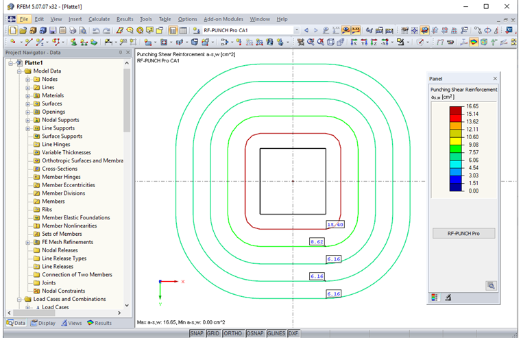
Summary
The rules for punching shear verification according to Eurocode 2 cannot be implemented effectively without a software solution. Examples include the calculation of the load increase factor β according to the model with fully plastic shear force distribution in the perimeter or the iterative determination of the position of the critical perimeter for foundations. Furthermore, building layouts are becoming ever more open and complex, so that rules for the application of possible simplifications are not met and therefore cannot be applied. By integrating the RF-STANZ Pro add-on module into the RFEM FEM program, all required data for the geometric determination of the critical perimeter as well as the design loads for the punching shear verification can be taken directly from the FEM input or FEM calculation. Thus, punching shear verification for columns, wall corners, and wall ends can be carried out very efficiently and conveniently. For columns, it is additionally possible to account for a column head reinforcement. The result evaluation of the carried out punching shear verifications is displayed in clear tables with all intermediate results required for the respective verifications. A graphical representation of the results such as required punching reinforcement, shear force distribution, and punching resistances is possible in the RFEM graphic window.