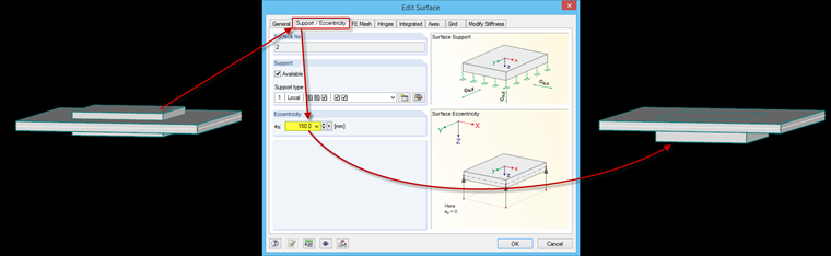
Eccentricity of Surfaces
Surfaces can be displaced into the local z-axis using the "Support/Eccentricity" tab of the "Edit Surface" dialog box. For example, this would be necessary if there was a plate thickness jump within a plate and the surface must remain planar. In this case, a new surface with a greater thickness is entered and integrated into the thinner plate, and the eccentricity is defined.
Eccentricity of Members
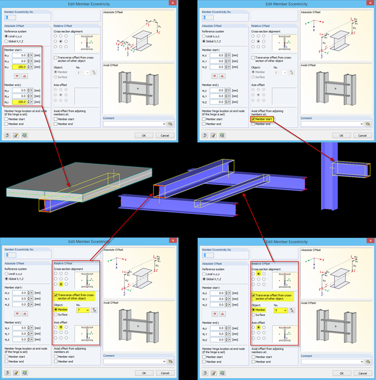
Members can be defined in the "Options" tab of the "Edit Member" dialog box, or you can create a new member. Absolute and relative offsets are available in the "Edit Member Eccentricity" dialog box.
You can select the absolute offset in reference to the global or local (member axis) axis system and enter the eccentricity as the absolute distance to the previously used system line.
In the case of the relative offset, you can define the member eccentricity depending on the particular cross-section and the adjacent structural component (member or surface).
Furthermore, it is possible to select the automatic axial offset from the adjoining members.
Considering Eccentricities in Calculation
Eccentricities should be used for more than simply achieving a realistic representation, since they also affect the deformation and internal forces.
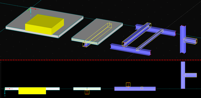
If you enter an eccentricity for a surface, additional entries are filled in the stiffness matrix to account for the influence of the eccentricity. As an alternative, it would also be theoretically possible to model the offset position of a surface using a shifted surface and connecting (rigid) surfaces. However, this can lead to significantly different results. The type of idealization should therefore be chosen carefully, depending on the structural geometry.

Similar to surfaces, the results for members also vary depending on the selected modeling.

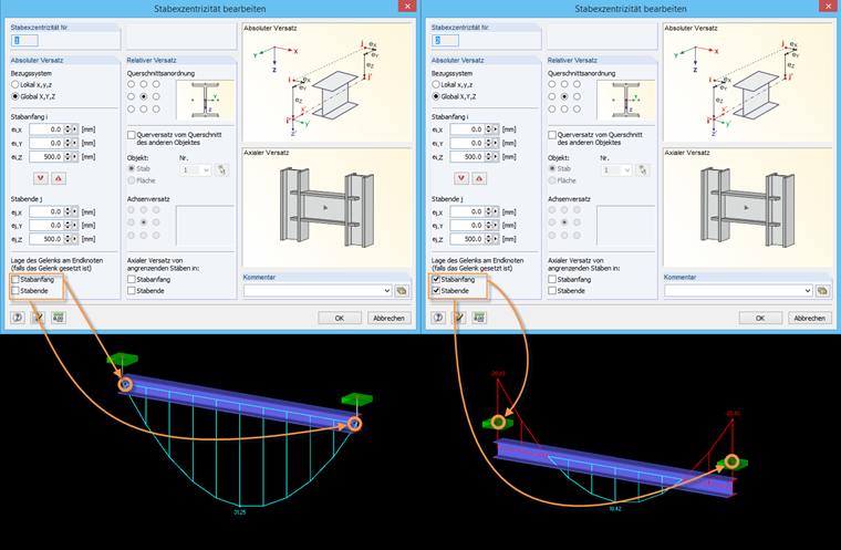
In RFEM in particular, it is possible to control the location of any existing member hinge in combination with the eccentricity. By default, these hinges are located in the shifted axis system. However, if the hinge should apply to the original node, you can set this separately for the member start and member end.