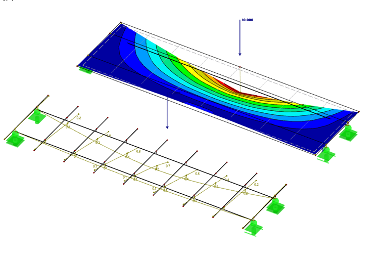
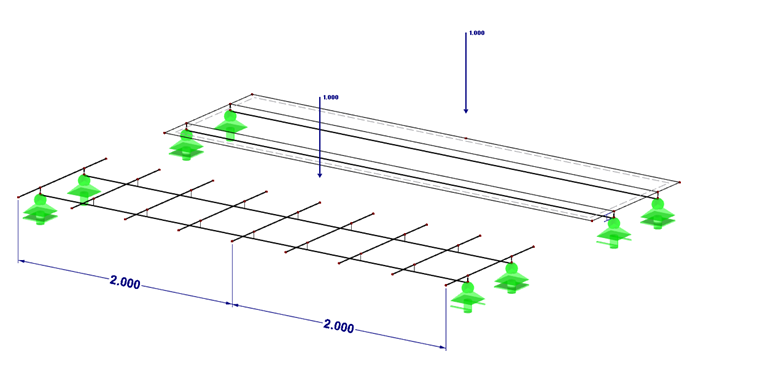
For example, [2] often recommends defining a girder grillage. The grillage represents very well the biaxial structural behavior of the concrete slab of a composite beam. However, the modeling effort is greater in this case, and the grillage is inaccurate on local discrete points. Below, the modeling of a girder grillage is compared with the modelling of an orthotropic plate.
First, the definition of the girder grilage is described using a simple structure. Then the orthotropic plate is defined. Finally, the results and the differences are explained.
System
- Cross-section steel: HE-A 200
- Material steel: S235
- Cross-section concrete: d = 100 mm
- Material concrete: C30/37
- Load: 5 kN/m²
- Poisson's ratio: nu = 0.2
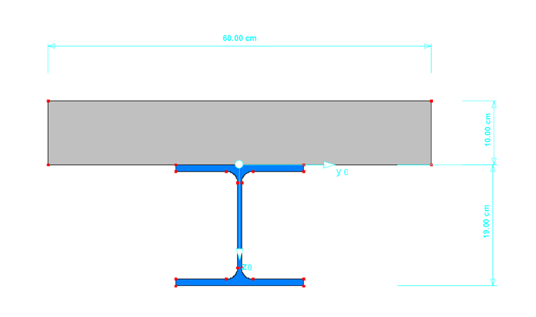
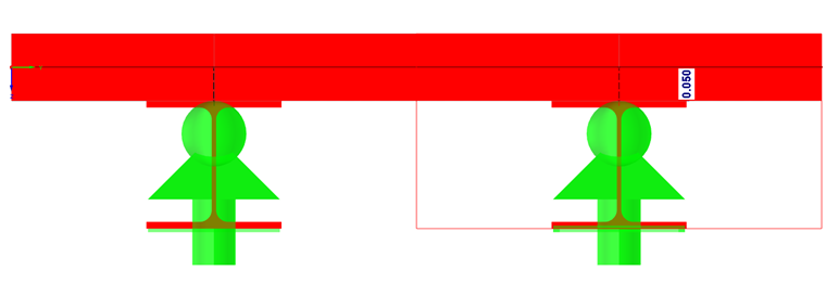
The composite cross-section is created in SHAPE-MASSIVE and imported into RFEM with the defined eccentricity of the cross-section to the concrete slab. The effective width of the cross-section is assumed to be 60 cm. The centroid of the cross-section is slightly shifted to the joint between the concrete and steel by 0.8 cm upwards. Therefore, the joint is taken into account for the supports. which are shifted by 5 cm downwards.
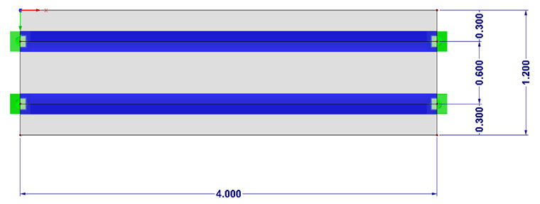
The support scheme itself was selected in such a way that no restraints occur due to restrained deformation.
The load is applied identically for both systems.
- LC1 = 5 kN/m²
- LC2 = 10 kN (x-direction = mid-span, y-direction = outer edge)
Girder Grillage Structure
Requirements of the girder grillage (from [1]):
- constant construction height
- straight girder bridge
- simple symmetrical cross-section
- Both main beams are supported on each support axis, which is perpendicular to the longitudinal axis of the bridge.
- Almost rigid transverse stiffeners in the support axes
- unrestrained warping in the support axes
- The structural engineering software for truss analysis must be able to calculate member elements.
Calculated value of bending stiffness (from [2]):
Calculated value of torsional stiffness:
Cross-section-properties:
- IT = 0 cm4
- Iy = (100cmx (10cm)³)/12 = 8,333.3 cm4
- A = 1,000 cm²
- Ay = 833 cm²
The entry is made in the program using the effective cross-section properties. The shear stiffness of the members is taken into account. Stiffness is determined for the concrete slab in the transverse direction (width = 1 m).
Orthotropic Plate Structure
In the orthotropic plate structure, the main beams are modeled in the same way as in the girder grillage. These girders are then integrated in the concrete flange. The stiffness is transferred completely by the main beams in the longitudinal direction and by the concrete flange in the transverse direction. The FE mesh size is defined identically to the distance of the secondary beam with 50 cm.
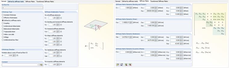
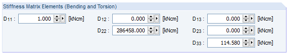
The stiffness matrix of the orthotropic plate is symmetrical and only applied to the main diagonals. The stiffnesses for bending in the longitudinal direction of the plate and torsion are defined identically to the transverse bars of the girder grillage with almost zero.
Calculated value of bending stiffness:
Calculated value of torsional stiffness:
In the program, data is entered using user-defined stiffnesses.
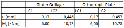
Summary