


General
The bases for internal forces are cross-section designs which are, in most cases, determined for loads with a known and fixed application point. However, when designing craneways or street bridges, movable live loads occur as well. The application points of these loads are variable in time.
To design a supporting structure, the maximum and minimum internal forces as well as the support reactions must be known. Influence lines can be used to find the governing load positions.
Determination of Influence Lines
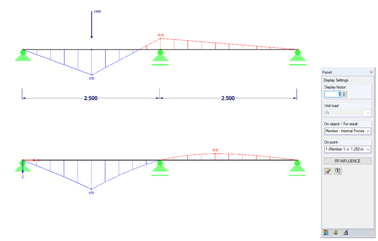
As concerns the non-moving load, the basis is the definition of a section for which the internal forces should be determined. The loading is applied with a unit load of which the load position is variable. Figure 01 shows the comparison of the evaluation of the internal force My for a non-moving load Fz with x = 1.25m and the influence line ηMy for a moving unit load Fz = 1 and the evaluation position x = 1.25 m.
To determine the influence line, a single load is "rolled" over the supporting structure and for each load position; the influence on the section to evaluate is recorded as ordinate η. The ordinates can be both positive and negative. If the ordinate has the value η = 0, it is also called a load separation point. At this location, the influence line cuts the baseline. A load applied at this location thus has no influence on the examined internal force. In Figure 01, this is the case as soon as the load is directly above the support.
If all end points of the determined ordinates are connected, this results in the influence line.
Evaluation of Influence Lines
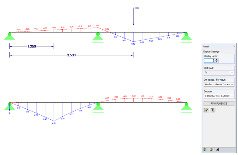
In Figure 02, the structural acting load has been applied at x = 3.50 m in the upper two-span beam. The influence line in the lower two-span beam is still evaluated for x = 1.25 m. The term "influence" should be clarified here. At location x = 1.25 m, it results in a moment My = -0.12 kNm, provided that the load Fz = 1.0 kN is at x = 3.50 m.
If the influence line ηMy is considered now, an ordinate η = -0.12 is located at x = 3.50 m.
Summary: Any load Fz that is located at x = 3.50 m generates a moment My = -0,12 ⋅ Fz at x = 1.25 m. (The value -0.12 is rounded. The pure value amounts to -0.11507.)
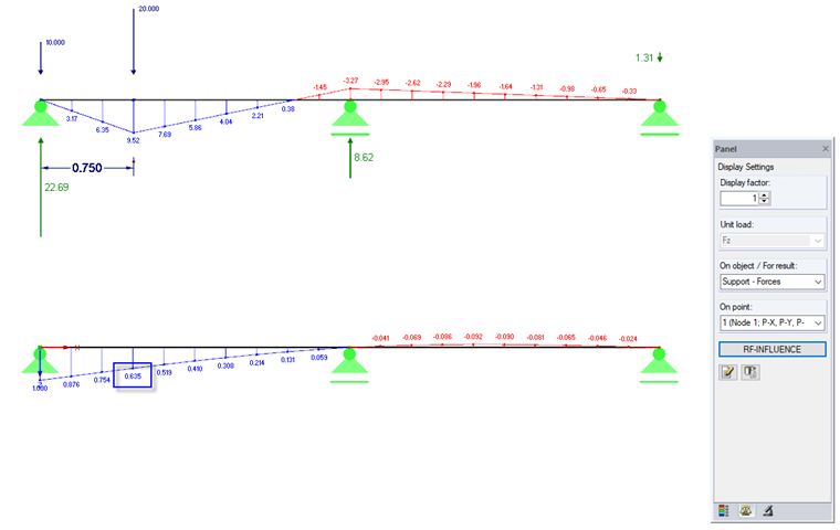
Another simple example in Figure 03 shows the evaluation of the influence line for the support force in the left support for a train load resulting from two single loads. The unit load Fz = 1 generates a force of 1.0 kN in the support. The ordinate η is thus 1.0. Any load P thus generates the force P ⋅ η in the support. If several loads are available, each single load Pi generates a force Pi ⋅ ηi in the support.
The support force results in:
Example from Figure 03:
To determine the maximum support load, the train load has to be placed in the positive area of the influence line. If the minimum should be determined, the train load has to be placed accordingly in the negative area.
General rule: To find an extreme value, the bigger load is positioned directly over the maximum value of the influence line. The graphical display of the influence line via RF-INFLUENCE is useful here.
Conclusion
Influence lines are used to find extreme values of support forces and internal forces of movable loads.
The shape of the influence line allows conclusions to be drawn about the governing loading to find a limit value at the evaluated section for the corresponding internal force.
The influence line is displayed over the whole length of the structural component to evaluate, but all indicated ordinates η describe the influence on a structural value at only one location of the beam.
RF-INFLUENCE is the tool to determine the influence lines of members and influence surfaces of surfaces for internal forces, support forces, and deformations.