


Load Increments for Iterative Calculation
When performing an analysis for a "sensitive" system close to stability failure, it is often difficult to find the equilibrium. Therefore, the program offers the option to apply the load incrementally: For example, if two load increments are specified, half of the load is applied in the first step. Iterations are carried out until the equilibrium is found. Then, in the second step, the complete load is applied to the already deformed system and iterations are run again until the state of equilibrium is reached. Calculation break-offs due to instabilities are thus avoided. Calculation by means of load increments inevitably has an unfavorable effect on the computing time. You can define load increments globally, as well as specific to load cases and load combinations.
RFEM also offers the option to save the results of the individual load increments during the calculation. Select the desired setting in the "Calculation Parameters" dialog box of the load case or load combination. It displays, for example, the force and moment distributions taking into account nonlinear effects, which may lead to distinct redistributions in the model.

This technical article shows three simple examples for iterative calculations that illustrate the gradual development of the results under increasing load levels.
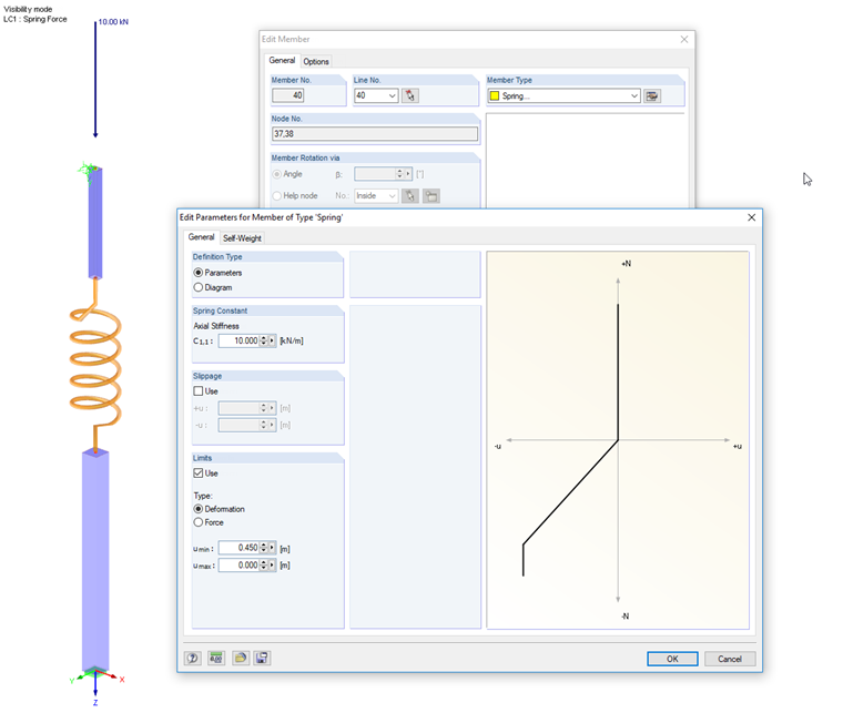
Spring with Limit
A telescopic rod under compression is represented by two pipes, and their displacements are controlled by a spring as intermediary. Define the axial stiffness of the spring and the limitation of the deformation or the force in the "Edit Parameters for Member Type 'Spring'" dialog box. In the example, the compressive force is no longer compensated if a shortening of 45 cm is achieved.
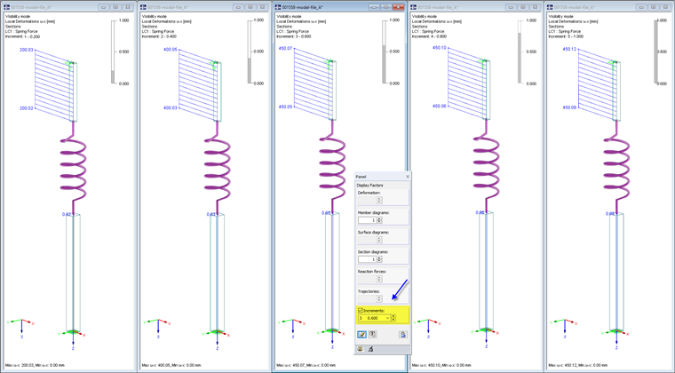
The nodal load is applied in five load increments. The calculation is carried out according to the linear static analysis. With 20% and 40% of the load, the deformation of the spring with 20 cm and 40 cm is in the effective workspace. The upper member is accordingly displaced downwards. If the load is increased to 60%, 80%, and finally 100%, the deformation no longer increases with a spring deflection of more than 45 cm. The deformation of the upper member remains constant. The tiny differences in the decimal places result from the shortening of tube members.
Frame with Diagonals Limited in Axial Force and Supports with Slippage
A frame is stiffened by means of crossing diagonals. The axial force resistance of the prestressed L-sections is controlled by a yield criterion: Only compressive forces up to 2 kN and tension forces up to 20 kN can be absorbed. Forces outside of this range increase the strain without absorbing any extra forces.
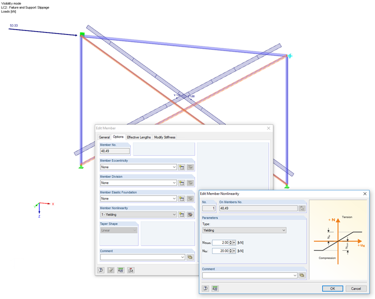
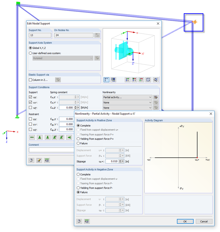
Moreover, a nonlinearly acting horizontal support with slippage is defined at one frame joint that represents an adjacent wall. It acts only for compressive forces as soon as a horizontal nodal displacement of 1 cm occurs.
The nodal load is applied in five load increments again. The calculation is performed according to the second-order analysis. In case of a load level of 20%, one diagonal is sufficient to displace the nodal load by means of a compressive force in the system. In the case of 40% of the load, a tension force additionally occurs in the second diagonal. Both diagonals already show a yielding behavior. They are, however, sufficient to stabilize the system without the horizontal support. This support is only effective from 60% of the load.
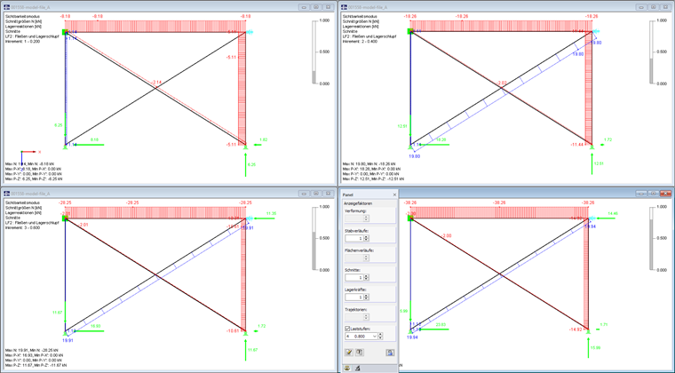
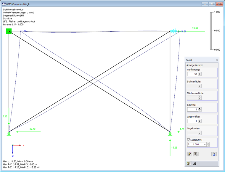
In the other load increments, the redistribution effects are completed. A total deformation of 10.01 mm occurs at the node that is now supported in the frame joint (taking into account the Z-ratio).
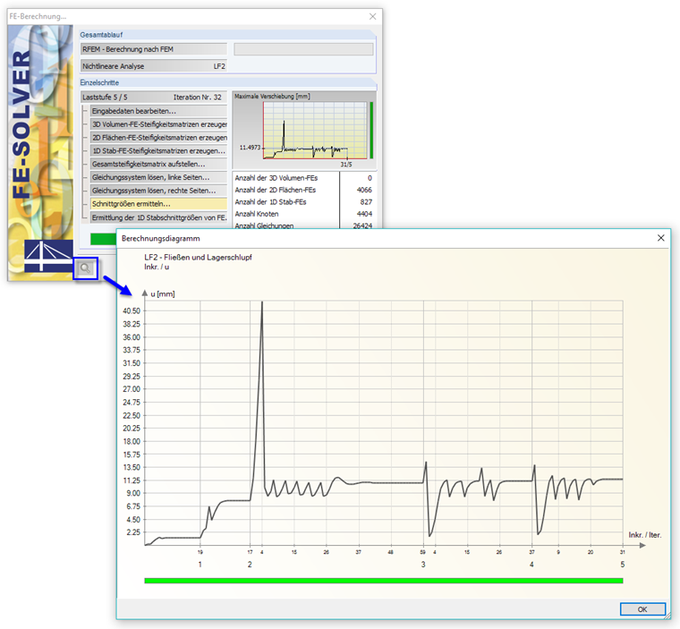
During the calculation, the distribution of the deformations (default) in the individual load increments is displayed as a diagram. If the deformations are in a tolerable range, the bar is green. A red bar means, in most cases, that there are overly large rotations (0.1 rad or more). You can access the calculation diagrams after the calculation in the "Calculation Parameters" dialog box, "Calculation diagrams" tab for a detailed evaluation.
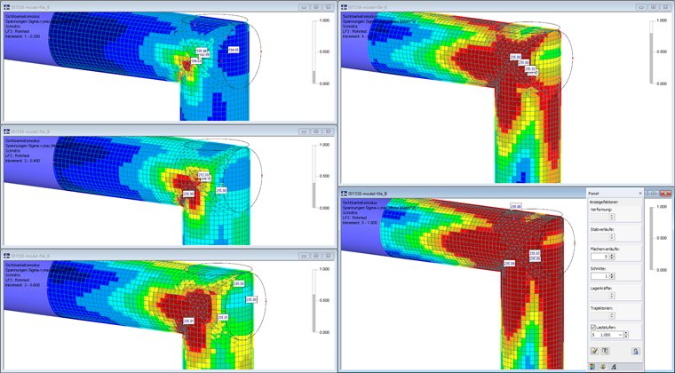
Frame Joint with Plastic Material Behavior
A frame made of tubular steel is loaded by a vertical load. This area is modeled by means of surface intersections for the plastic analysis of a frame joint. The surfaces have an isotropic plastic material behavior: When reaching the yield stress of 235 N/mm², the stress cannot continue to increase.
The RF-MAT NL add-on module is required to analyze the nonlinear material behavior. Five load increments are applied again. The results of the equivalent stresses show the progress of the plastification on the individual load levels. To evaluate the plastic analysis, the stress distribution "Constant on elements" should be selected (see also Knowledge Base: Smoothing Options).
Conclusion
This article shows some simple examples to calculate load increments. This approach is basically suitable for sensitive systems or considering larger deformations, but can also be used for specific analyses of the structural behavior with regard to redistributions or nonlinear effects.
When performing nonlinear calculations, it is necessary to have a sufficiently high number of iterations. If no convergence arises within this limit, an appropriate message will be displayed at the end of the calculation. The results of the incomplete analysis can be accessed afterwards to identify issues or adjust the calculation parameters.
The results graphics of the individual load increments can be documented in the printout report and thus be used for better understanding of the structural analysis.