


The example presented in this article deals with the classification and cross-section designs of a general cross-section using SHAPE-THIN. In order to allow a comparison with the RF-/STEEL EC3 add-on module, the "general" cross-section shown here is a double-symmetric I-section. There is loading due to compression and biaxial bending. The cross-section designs are performed by taking into account the maximum c/t ratios of cross-section parts subjected to compression. A special feature here is the application of the stress distribution by means of the compression zone factor α.
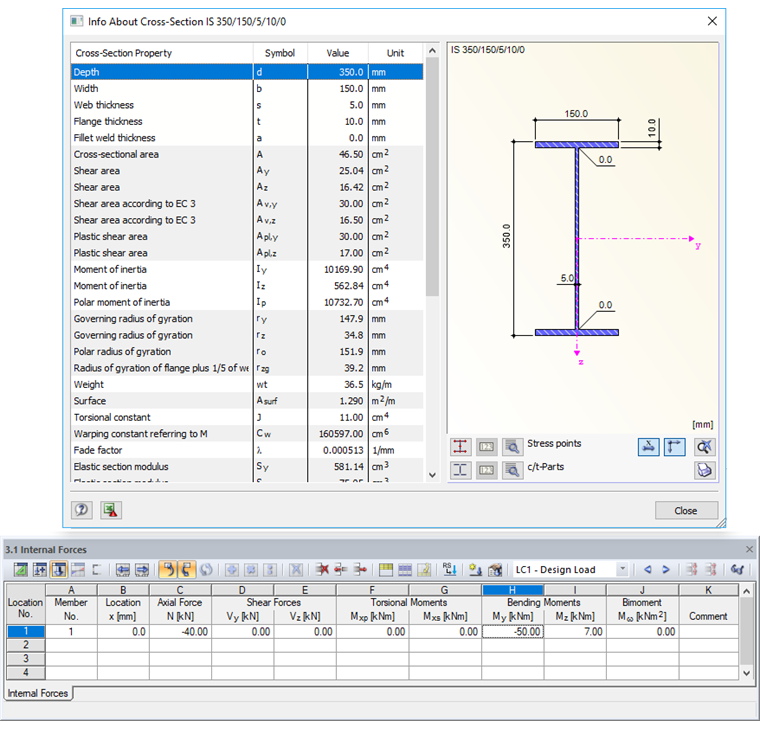
Determining Effective Cross-Section Properties According to EN 1993-1-1
The stress diagrams shown in Image 02 result from the default settings. Due to the relatively slender web, the cross-section is classified in cross-section Class 3 for the given loading.
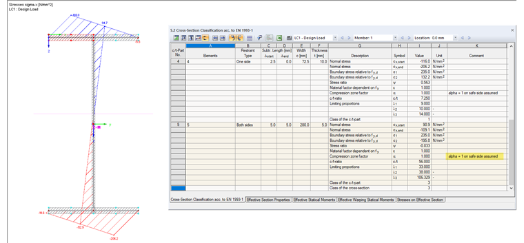
The neutral axis is clearly visible in the web. Although a relatively large area of the corresponding c/t section has no compression stresses, the entire web is considered as being subjected to compression: In Result Table 5.2, the compression zone factor α = 1 is shown as "assumed on the safe side" for c/t part No. 5. This assumption is justified by the fact that the c/t limit values of cross-section parts subjected to compression specified in the Eurocode apply only to certain cross-sectional shapes. According to [1], Table 5.2, this results in the following limit slenderness for Class 2:
Due to the given c/t ratio of 56.00, the cross-section is classified in Class 3. Only elastic design is possible here because local buckling effects may occur.
SHAPE-THIN provides the option to consider the actual stress distribution when determining the compression zone factor. In the "Calculation Parameters" dialog box, "c/t Parts and Effective Cross-Section" tab, activate the calculation according to the simplex method.
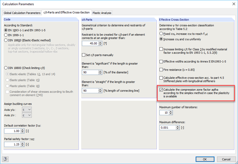
When using the simplex method, the cross-section is discretized by means of surface particles and the yielding is approximated as a linear optimization task [2].
The recalculation results in the compression zone factor α = 0.594. This value leads to a cross-section classification in Class 1, as the corresponding limit slenderness is met:
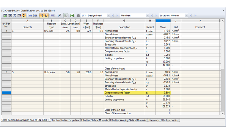
Cross-section Class 1 allows a more economical design, since the plastic cross-section reserves can be utilized.
Plastic Resistance Design According to Simplex Method
As mentioned above, you can perform an analysis of the plastic cross-section resistance independently of the standard with SHAPE-THIN. The simplex method cannot be used solely to determine the compression zone factor α. However, it is also an excellent option for the plastic analysis of any cross-sections. The iterative determination of the plastic resistance by means of surface particles is described in [2], Section 8.9.
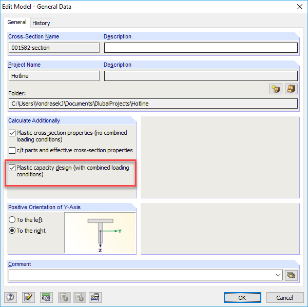
For the simplex calculation option, select "Plastic capacity design" in the General Data.
SHAPE-THIN determines the stresses with an iterative method that occur when the simplex particles are successively plastified. After the calculation, you can check the simplex elements with their plastic stresses in the cross-section graphic.
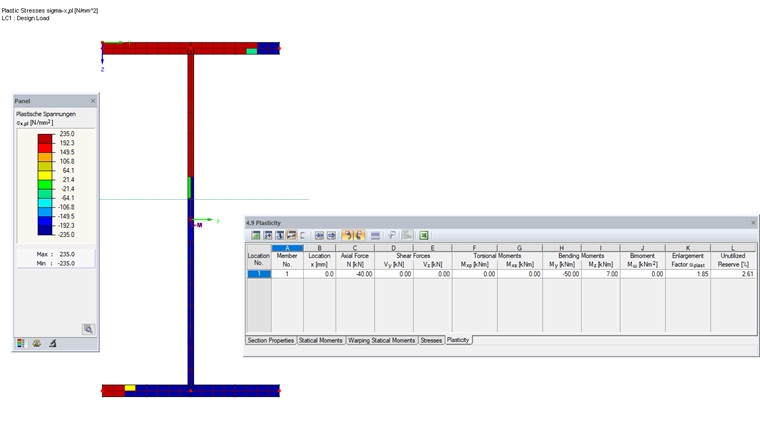
Table 4.9 shows the enlargement factor as αplast = 1.85. This means that the given constellation of internal forces multiplied by the factor 1.85 leads to the full plastic state being reached. The "Unutilized Reserve" is determined from the proportion of simplex elements in which the yield point has not yet been reached. They are displayed in yellow and green in the stress diagram.
For comparison: The elastic ratio of the cross-section is 88%.
Comparison with RF-/STEEL EC3
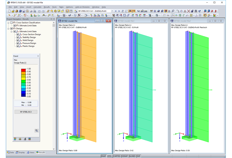
To compare, a member model is created in RFEM or RSTAB and the corresponding internal forces are applied. The following design cases (each without stability analysis) are analyzed in the RF-/STEEL EC3 add-on module:
Case 1
The SHAPE-THIN cross-section is designed. Since cross-section types of the section properties software are usually assumed as "general" and thus assumed as "on the safe side" (see above), this results in classification in cross-section Class 3. The elastic design provides a ratio of 88% and thus confirms the SHAPE-THIN results. No plastic design that takes yielding zones into account is possible for arbitrary cross-section shapes in RF-/STEEL EC3.
Case 2
The design is carried out for an equivalent IS-section. The design results in a classification in cross-section Class 1 for a limiting slenderness of 59.72. The design is performed according to [1], Equation (4.15) as follows: Taking into account the plastic moment resistance, this results in a ratio of 42%. This value is smaller according to the simplex method (enlargement factor αplast = 1.85). According to the approximate formulas of the Eurocode, the relatively small axial force does not have to be considered for the plastic moment resistance. The result is thus on the unsafe side.
Case 3
The RF-/STEEL Plasticity add-on module determines a ratio of 59% for the SHAPE-THIN section according to the partial internal forces method. As in SHAPE-THIN, the design according to the simplex method results in a design ratio of 54% (1/1.85 = 0.54).
Conclusion
The SHAPE-THIN cross-section software determines the stress distributions for any section's geometries and analyzes the c/t ratios that govern for the classification of the cross-section. If there is a stress distribution with an alternating sign in a c/t part, the compression zone factor is assumed to be on the safe side at 1.00 and the entire cross-section part is considered to be subjected to compression. This is the default setting in the program, because the limit values of the c/t ratios specified in the Eurocode apply only to certain cross-section shapes and not necessarily to general geometries that are usually analyzed with SHAPE-THIN.
The compression zone factor can be determined with the simplex method in order to consider the actual stress distribution for the classification. In most cases, the maximum c/t ratios of cross-section parts subjected to compression will not correspond to the assumptions mentioned in the Eurocode. Therefore, we recommend checking the calculation of the plastic resistance independently of the standard according to the simplex method. If the enlargement factor αplast is greater than 1, plastic reserves are present in the cross-section.
In accordance with its intended use, SHAPE-THIN determines the cross-section resistance. Stability designs for structural components have to be performed separately, for example in the RF-/STEEL EC3 add-on module for RFEM or RSTAB. You can also consider warping effects with the RF-/STEEL Warping Torsion add-on module.