


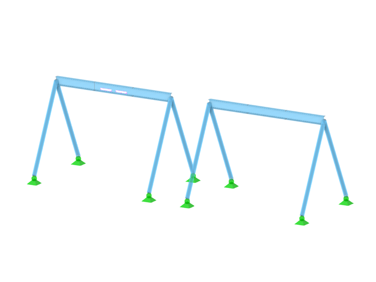
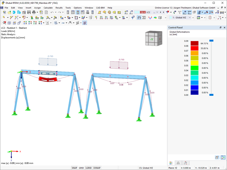
The example shown in Image 01 consists of a single-span beam supported on four columns, each in two different designs; one is represented as a pure member model (right), and one is defined as a member of the surface model type for the middle part of the beam.
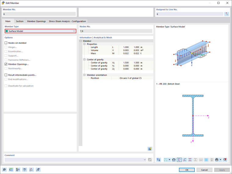
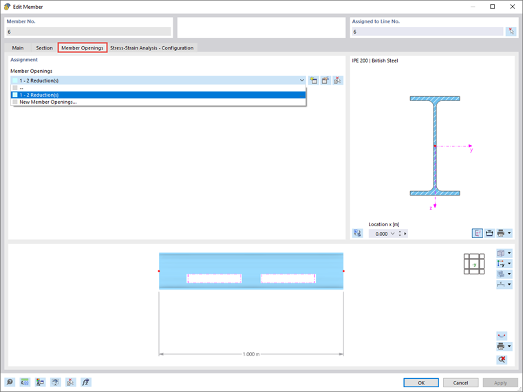
In the Edit Member dialog box, under Member Type, it is possible to select Surface Model. Once it is selected, you will also be given the option to insert Member Openings, as shown in Image 02.
When the Surface Model member type is set, the member is available both as a member model and as a surface system. Two options for switching the rendering between the two model types are shown in Image 03, once via the Display navigator and once by clicking the corresponding button.
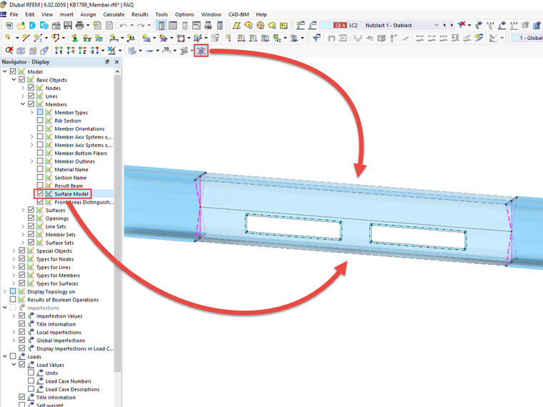
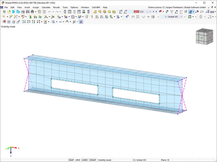
Image 04 shows the isolated surface model of a member. The FE mesh used is specified by the program based on surface mesh refinements; the surface thicknesses are defined by the selected cross-section. A web of rigid members can be seen at both ends of the surface model. These members are used to transfer the surface internal forces and moments to the connected members.
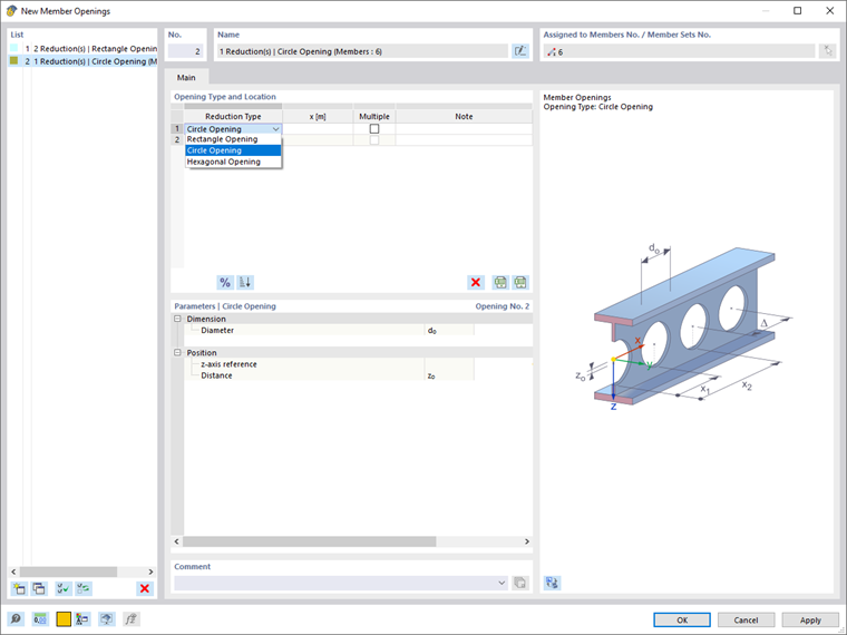
The Member Openings option is available for inserting openings or perforations into the cross-section's web. In the tab specially set up for this purpose, existing openings can be selected from a list (Image 05) or newly inserted (Image 06). The defined member openings can be found under the Types for Members in the navigator.
The Static Analysis is performed for the surface model. Both member and surface results can then be used for evaluation. Image 07 shows a comparison of the modeling from Image 01 using the global deformations.
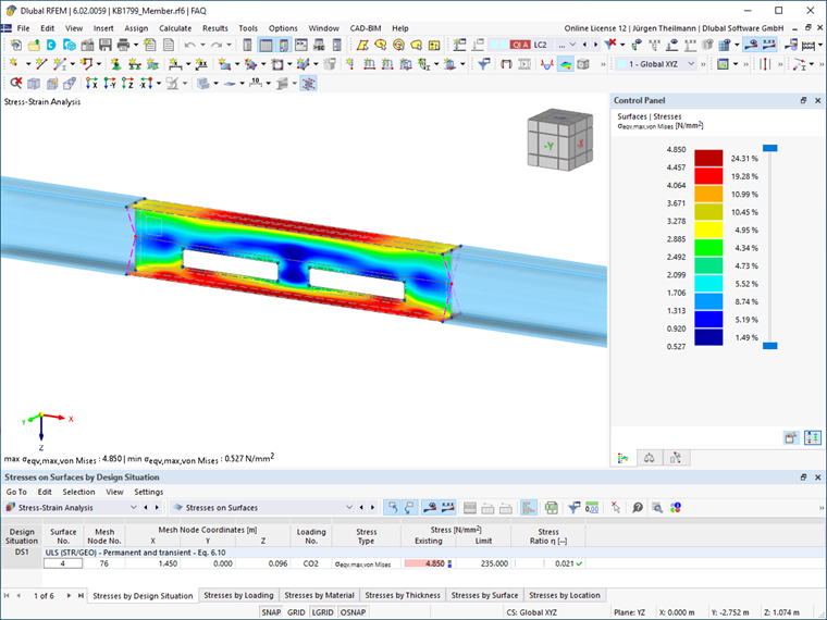
The surface internal forces can also be further processed, for example, in the Stress-Strain Analysis add-on. An analysis of the stress distribution in the surface model is shown in Image 08.
Conclusion
Using the Surface Model member type, members can easily be designed as surface models. The modeling is just as intuitive and easy as with any other member type. The transfer of the internal forces and moments from the surface model to the connected members is ensured by the program, using automatically generated rigid members. In addition, member openings can be created and taken into account in the calculation.
