


Member openings offer the possibility of inserting cutouts or holes into a member element. This way, you can include, for example, castellated beams in the structural model.
Opening Type and Location
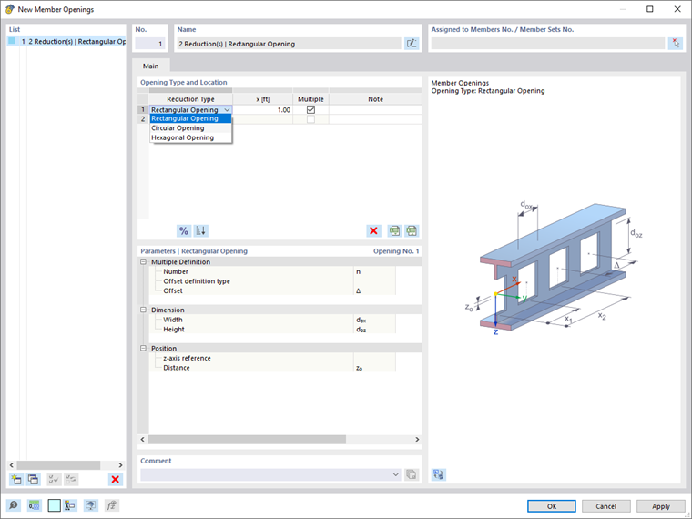
The following opening types can be selected from the list (see the image above):
- Rectangular Opening – for ventilation ducts or supply lines
- Circular Opening – for castellated beams with circular holes
- Hexagonal Opening – for castellated beams
The definition options in the "Parameters" dialog section are adapted to the reduction type.
Enter the location "x" where the opening is located. It describes the distance from the start node of the member and refers to the center of the opening.
If there are several similar member openings available at regular intervals along the member, as for a castellated beam, activate the "Multiple" check box. You can then define the offset of the openings in the "Parameters" dialog section.
Parameters
In this dialog section, you specify the dimensions of the opening. The parameters of the individual reduction types are illustrated in the dialog graphic.
If the opening is not lying in the member's center of gravity, you can adjust the "Position". In the "z-axis reference" list, specify the point of the cross-section that is to be used as the reference:
- Top
- Center
- Bottom
"Top" and "Bottom" are determined by the orientation of the local member axis z (see the image Member Axes).
Then, specify the "Distance" zo to move the opening along the z-axis. This value is related to the center of the opening, too.