


To validate the calculation performed using RFEM 6, an example described in DIN 4017, Supplement 1 (2006) [1] is used. The analysis focuses on a foundation subjected to a centrally and vertically applied load on layered subsoil, and the results are compared with the values determined in RFEM 6. The objective of this analysis is to determine the bearing resistance of the soil beneath the foundation base.
Model Description
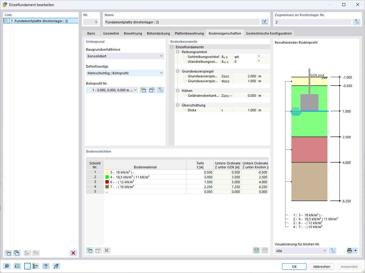
The underlying foundation is rectangular, measuring 4.0 m × 5.0 m, with a thickness of 1.0 m. The top of the foundation is 1.0 m below ground level, so the bottom of the foundation is at a depth of 2.0 m. The ground water level is also 2.0 m below ground level, that is, directly at the level of the foundation base. The geometry and the governing soil layers, along with their associated properties, are displayed below.

Soil Layers and Parameters
| 123 | Specific Weight – Moist γ | Specific Weight – Buoyancy γ‘ | Friction Angle φ‘ | Cohesion c’ | Layer Thickness |
| 1 | 18 kN/m3 | - | - | - | 0.5 m |
| 2 | 18.5 kN/m3 | 11 kN/m3 | 30° | 0 kN/m3 | 3 m |
| 3 | - | 12 kN/m3 | 25° | 5 kN/m3 | 1.5 m |
| 4 | - | 10 kN/m3 | 22.5° | 2 kN/m3 | 2.25 m |
Manual Calculation According to DIN 4017, Supplement 1 (2006)
Iterative Determination of Governing Soil Properties φm
According to DIN 4017 [2], the friction angle φ' may be averaged for layered subsoil if the individual values of the underlying layers do not deviate by more than 5° from the common arithmetic mean φav.
In this example, there are three soil layers directly beneath the foundation. For these layers, the friction angles are φ'2 = 30°, φ'3 = 25°, and φ'4 = 22.5°. The arithmetic mean value is calculated as φav = ∑ φ'i/n = (30 + 25 + 22.5)/3 = 25.83°.
The deviation from the mean value is thus less than 5°.
1st Iteration Step (Starting with φm,0 = 25.83°; α = β = δ = 0):
ϵ1 = asin(−sin(β)/sin(φA,k)) = asin(−sin(0.00°)/sin(25.83°)) = 0.00° – according to A.2
ϵ2 = asin(−sin(δ)/sin(φA,k)) = asin(−sin(0.00°)/sin(25.83°)) = 0.00° – according to A.5
ϑ1 = 45° − φm,0/2 − (ϵ1 + β)/2 = 45° − 25.83°/2 − 0 = 32.1° – A.1
ϑ2 = ϑ3 = 45° + φm,0/2 − (ϵ2 + β)/2 = 45° + 25.83°/2 − 0 = 57.9° – A.3
υ = 180° − α − β − ϑ1 − ϑ2 = 180° − 0° − 0° − 32.1° − 57.9° = 90° – A.6
r2 = B'/(2⋅cos(ϑ2)) = 4.00 m/(2⋅cos(57.9°)) = 3.76 m – A.7
r1 = r2⋅e(0.5π⋅tan(φm,0)) = 3.76 m⋅e(0.5π⋅tan(25.83°)) = 8.03 m – A.8
ls = (r1 − r2)/sin(φ) = (3.76 m − 8.03 m)/sin(25.83°) = 9.80 m – A.17
Total length of the slip line according to Figure 3 of this supplement:
Σl = r2 + r1 + ls = 3.76 + 8.03 + 9.81 = 21.60 m
l1 = (z3 − d)/(sin(ψ2)) = 1.50/0.847 = 1.77 m
l2 = (z4 − z3)/(sin(ψ2)) = 1.50/0.847 = 1.77 m
l4 = (z3 − d)/(sin(ψ1)) = 1.50/0.531 = 2.82 m
l5 = (z4 − z3)/(sin(ψ1)) = 1.50/0.531 = 2.82 m
l3 + l6 + ls = Σl − (l1 + l2 + l4 + l5) = 21.60 m − 2⋅(1.77 + 2.82) = 12.42 m
φ'2 = (4.59⋅30.0° + 4.59⋅25.0° + 12.42⋅22.5°)/21.60 = 24.6°
c'2 = (4.59⋅5.00 + 12.42⋅2.00)/21.60 = 2.2 kN/m2
The iteration is repeated with φ'2 = 24.6°.
2nd Iteration Step (with φm,1 = 24.6°; α = β = δ = 0):
ϵ1 = ϵ2 = 0.00°
ϑ1 = 45° − 24.6°/2 − 0 = 32.7°
ϑ2 = ϑ3 = 45° + 24.6°/2 − 0 = 57.3°
υ = 180° − 0° − 0° − 32.7° − 57.3° = 90°
r2 = 4.00 m/(2⋅cos(57.3°)) = 3.70 m
r1 = 3.70 m⋅e(0.5π⋅tan(24.6°)) = 7.60 m
ls = |7.60 − 3.70| m/sin(24.6°) = 9.36 m
Σl = 3.70 + 7.60 + 9.36 = 20.66 m
l1 = l2 = 1.50/0.842 = 1.78 m
l4 = l5 = 1.50/0.540 = 2.78 m
l3 + l6 + ls = Σl − (l1 + l2 + l4 + l5) = 20.66 − 2⋅(1.78 + 2.78) = 11.54 m
Weighted mean values:
φ'3 = ((l1 + l4)⋅30.0° + (l2 + l5)⋅25.0° + (l3 + l6 + ls)⋅22.5°)/Σl
= ((1.78 + 2.78)⋅30.0° + (1.78 + 2.78)⋅25.0° + 11.54⋅22.5°)/20.66 = 24.71°
c'3 = ((l1 + l4)⋅5.00 + (l3 + l6 + ls)⋅2.00)/Σl
= ((1.78 + 2.78)⋅5.00 + 11.54⋅2.00)/20.66 = 2.22 kN/m2
Result: The governing friction angle has thus practically converged at φm ≈ 24.7°.
Partial Areas of Slip Body
Triangle ABD
ϑ2 = ϑ3 = 45° + 24.7°/2 = 57.35°
Aa = tan(ϑ2) ⋅ (B'/2)2 = 1.56 ⋅ 4.00 m2 = 6.24 m2
Triangle BCE
ϑ1 = 45° − 24.7°/2 = 32.65°
r2 = 4.00 m/(2⋅cos(57.35°)) = 3.71 m
r1 = 3.71 m ⋅ e(π/2 ⋅ tan(24.7°)) = 7.64 m
Ap = r12 ⋅ sin(ϑ1) ⋅ cos(ϑ1) = 26.54 m2
Partial Area of Spiral
As = (r12 − r22)/(4⋅tan(φ')) = 24.24 m2
Sum of Areas
ΣA = 57.02 m2
Average Weights of Slip Body
The average weights γ' can be determined from the partial areas and the respective layer weights:
γ' = (11.0⋅22.82 + 12.0⋅17.87 + 10.0⋅16.33) ÷ 57.02 = 11.0 kN/m3.
The average density of the soil adjacent to and above the foundation:
γ = (0.50 m⋅18.0 kN/m3 + 1.50 m⋅18.5 kN/m3) ÷ 2.00 m = 18.375 kN/m3
Calculation of Ground Failure Resistance
Now, the bearing capacity coefficients can be determined.
- Nq,0 = e(π⋅tan(24.7°)) ⋅ tan²(45° + 24.7°/2) = 10.33 [−]
- Nγ,0 = (10.33 − 1) ⋅ tan(24.7°) = 4.29 [−]
- Nc,0 = (10.33 − 1) ⋅ tan(24.7°) = 20.28 [−]
To account for the effect of the foundation geometry, additional shape coefficients are required:
- νq = 1 + 4.00 m/5.00 m ⋅ sin(24.7°) = 1.334 [−]
- νγ = 1 − 0.3 ⋅ 4.00 m/5.00 m = 0.760 [−]
- νc = (1.334 ⋅ 10.33 − 1)/(10.33 − 1) = 1.370 [−]
These factors result in the corrected bearing capacity coefficients:
- Nq = Nq,0 ⋅ νq = 10.33 ⋅ 1.334 = 13.78
- Nγ = Nγ,0 ⋅ νγ = 4.29 ⋅ 0.760 = 3.26
- Nc = Nc,0 ⋅ νc = 20.28 ⋅ 1.370 = 27.78
\[
\text{R}_n
= 5{,}00\,\text{m}\cdot 4{,}00\,\text{m}\cdot
\left(
\underbrace{11{,}0\,\text{kN/m}^3\cdot 4{,}00\,\text{m}\cdot 3{,}26}_{\gamma' \cdot B' \cdot N_\gamma}
+\underbrace{18{,}375\,\text{kN/m}^3\cdot 2\,\text{m}\cdot 13{,}78}_{\gamma \cdot t \cdot N_q}
+\underbrace{2{,}2\,\text{kN/m}^2\cdot 27{,}78}_{c' \cdot N_c}
\right) = 14\,233\,\text{kN}.
\]
Calculation in RFEM 6
In RFEM 6, geometry, loads, and layer parameters are defined in the same way. In contrast to the supplementary sheet method, the slip line is continuously integrated as a logarithmic spiral over the entire curve (no linearization in tangent and circular arcs). This ensures that the entire effective contact area of the sliding joint is included in the averaging, and the components of the individual layers are determined as actual surface contributions.
Result of the average friction angle: φm,RFEM = 25.03°
Bearing resistance: Rk,RFEM = A ⋅ σR,k = 5.00 m ⋅ 4.00 m ⋅ 741.53 kN/m² = 14,830.64 kN

Why does RFEM calculate 25.03°, while the manual calculation yields approximately 24.7°—and what does that mean for Rk?
In the manual calculation (supplement), the friction surface is discretized, that is, divided into tangent and circular arc segments. This results in a length-weighted average angle; the method is approximate and is refined iteratively (1st iteration ≈ 24.6°, 2nd iteration ≈ 24.71°).
On the other hand, RFEM 6 continuously integrates the local directions along the curve. This ensures that the area contributions of the layers at the slip joint are fully included (rather than just over segment lengths), the reference direction is handled unambiguously, and the curvature of the spiral is accounted for without linearization.
The effect in this example: The component of the “stronger” layer (with φ′ = 30°) contributes slightly more to the effective slip joint area than in the discrete approximation. This shifts the weighted average slightly upward, resulting in φm,RFEM = 25.03° (difference ~0.27° from the manual calculation).
Effect on Resistance Rk
A slightly larger φ scales the bearing capacity coefficients nonlinearly, thereby increasing the resistance.
Manual Calculation (Supplement):
Characteristic resistance stress σR,k = 710.97 kN/m²
Total resistance Rk = 14,233 kN
RFEM 6:
Characteristic resistance stress σR,k = 741.53 kN/m²
Total resistance Rk = 14,830.64 kN
The difference in Rn is ≈ 4.2% (related to the manual calculation). This is technically consistent and results directly from the methodology: discrete length weighting vs. continuous area weighting along the actually curved slip line.
Comparison of Results
| Method | Friction Angle φ [°] | Bearing Resistance Rn [kN] |
| Manual calculation (DIN 4017) | 24.7° | 14,233 kN |
| RFEM 6 | 25.03° | 14,830.64 kN |
Conclusion
The calculations according to DIN 4017 and the results in RFEM 6 agree very well. The slight discrepancy can be explained by the methodology (discrete approximation vs. continuous integration). In practice, this means that RFEM 6 reliably models manual calculations, reduces the need for manual iteration, and provides a mathematically more rigorous treatment of the slip line—while offering a transparent result display.