75 Results
View Results:
Sort by:
With the latest version of CONCRETE and RF-CONCRETE Members, it is possible to perform shear design for the connection of compression and tension flanges on a T-beam web.

In order to design longitudinal reinforcement for the serviceability limit state, it is necessary to enable this function. This is possible in Window 1.1 General Data under the "Serviceability Limit State" tab. After you select the "Analytical..." method of checking, you can select the corresponding additional options in the section for determining the longitudinal reinforcement of the "Settings of Analytical Method of Serviceability Limit State Design" window.

In RF-CONCRETE Surfaces, you can use the "Filter Points" function when evaluating results by points. This filter function allows for a user-defined group of points that can be defined in the result window. You can select the filter in Window 2.3 Required Reinforcement by Points, among others.
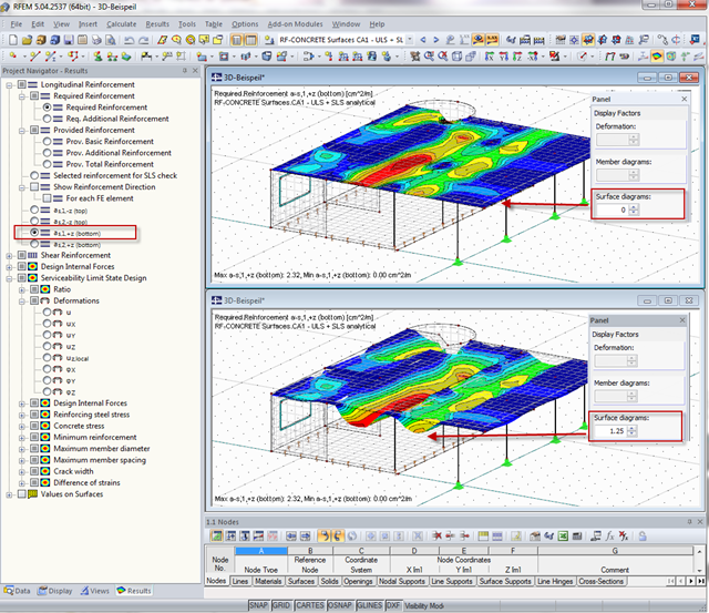
When calculating the surface reinforcement in RF-CONCRETE Surfaces, the result values for both surface sides +/- z are available. A previous post describes how to display the local surface sides in RFEM.
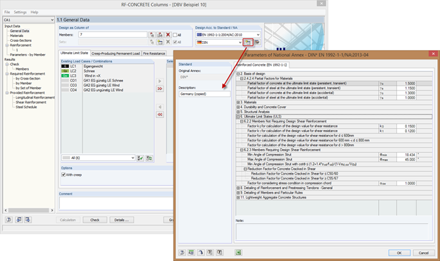
In order to meet the requirements for the parameters of special buildings modified according to standard adjustments, you can create new National Annexes from an existing one. To do this, copy the National Annex and adjust the parameters to the requirements.
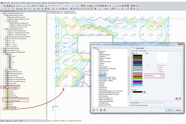
You can document the results of RF‑CONCRETE Surfaces graphically in the printout report. To do this, the "Values on Surfaces" setting is often selected in the Results Navigator of RF‑CONCRETE Surfaces. A text bubble including a result value is displayed, and depending on the settings in the Results Navigator, it can be displayed on the surface grid points, manually defined points, or in FE mesh points.
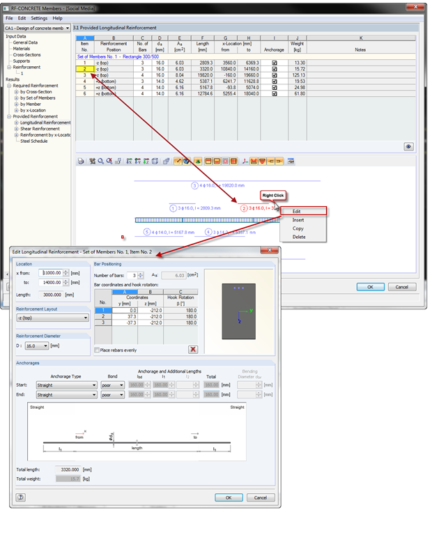
With the introduction of OSG graphics for the representation of design reinforcement in RF‑CONCRETE Members and CONCRETE, you can also select the reinforcement position directly in the graphic. Right-click the mouse to open the context menu where you can edit, copy, or delete the selected reinforcement position.
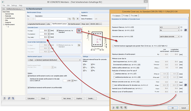
RF-/CONCRETE automatically determines the minimum concrete cover according to the standard. The calculation is based on the exposure class, the abrasion class, and the concrete cast.
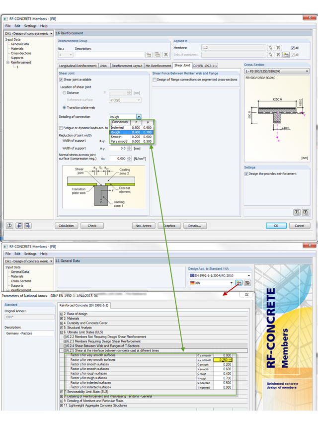
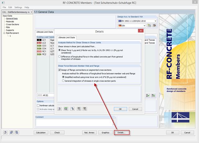
The shear resistance design value of a joint depends mainly on the formation or the roughness of the connection. When determining the ultimate limit state, this is considered by the factors µ (friction) and c (adhesion percentage of the contact area of the composite concrete).
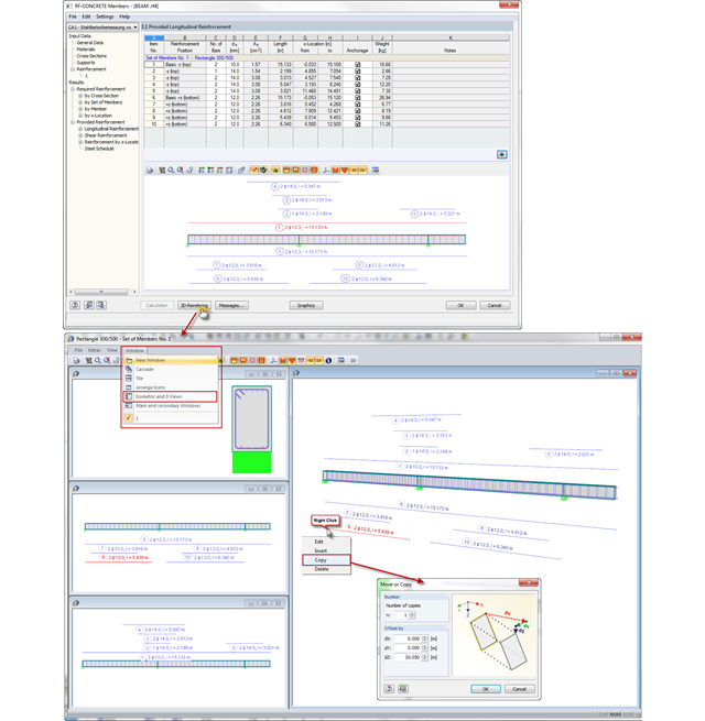
In CONCRETE and RF‑CONCRETE Members, you can open a dialog box with a 3D rendering of the existing reinforcement in Window 3.1 or 3.2. Now, you can also display different reinforcement views in several dialog boxes at the same time. The "Isometric and 3 Views" option known from RFEM is available here as well.
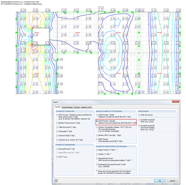
RF‑CONCRETE Surfaces performs the ultimate and the serviceability limit state design of slabs, plates, folded plates, and shells. In RFEM 5, the reinforcement resulting from this design can be displayed graphically on the surfaces of the structure using isolines. For the reinforcement design, it may be useful to export the results as isoline distribution in a DXF file in order to open them in a CAD application as background layers.
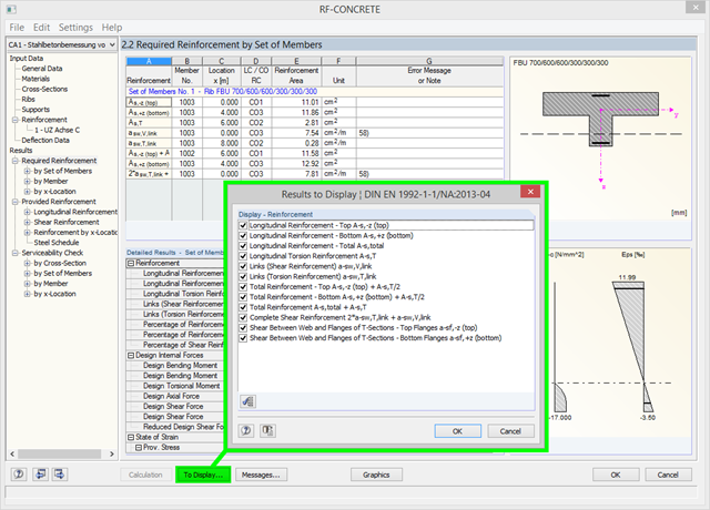
Using the [To Display…] button, you can specify the amount of reinforcement to be displayed in the results of the required reinforcement in Window 2.2 of RF‑CONCRETE and CONCRETE. In addition to the default setting, you can display the resulting reinforcement amount as (for example) the sum of the longitudinal and longitudinal torsion reinforcement, or the sum of the torsion and shear reinforcement. You can also reduce the number of preset results, of course.

The national parameters of EN 1992‑1‑1 for each country can be exported from RF‑/CONCRETE, RF‑/CONCRETE Columns, and RF‑/FOUNDATION Pro. To do this, there are interfaces with MS Excel, OpenOffice, and CSV. By exporting the national parameters, you can edit them in (for example) MS Excel, and display possible differences between the individual National Annexes clearly (see the image).
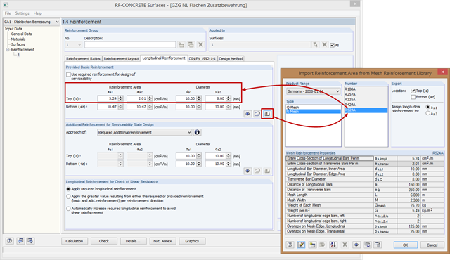
In RF-CONCRETE Surfaces, the reinforcement areas of the mesh reinforcement for basic and additional reinforcement are not entered manually, but you can select them in the library. Therefore, various product ranges are available (for example, from Germany, Austria, and the United States).
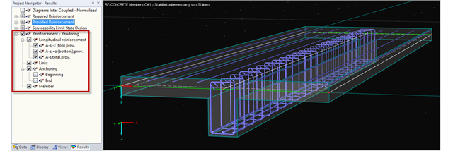
You can display the existing reinforcement of RF-CONCRETE Members not only in the module, but also in the RFEM graphical window and thus show the reinforcement for all members of the relevant RF-CONCRETE case.
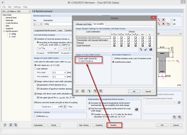
Starting with program version X.06, you can set in RF‑CONCRETE Members or CONCRETE whether the crack width analysis should be performed in any case, or only when exceeding the effective tensile strength of concrete.
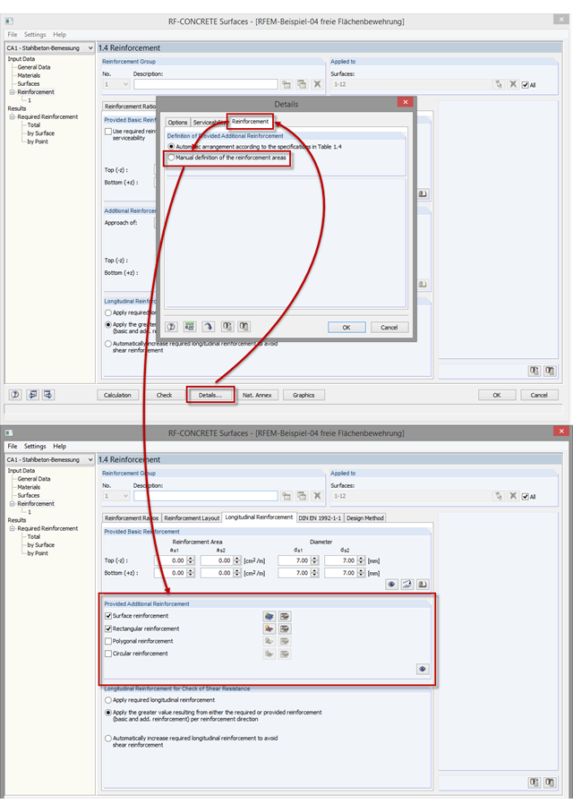
As of program version RFEM 5.06, you can not only perform the automatic arrangement of an additional reinforcement, but also define the surface reinforcement manually. In addition to the uniformly distributed basic reinforcement, you can define various surface reinforcements (per surface; rectangular, circular, or polygonal).
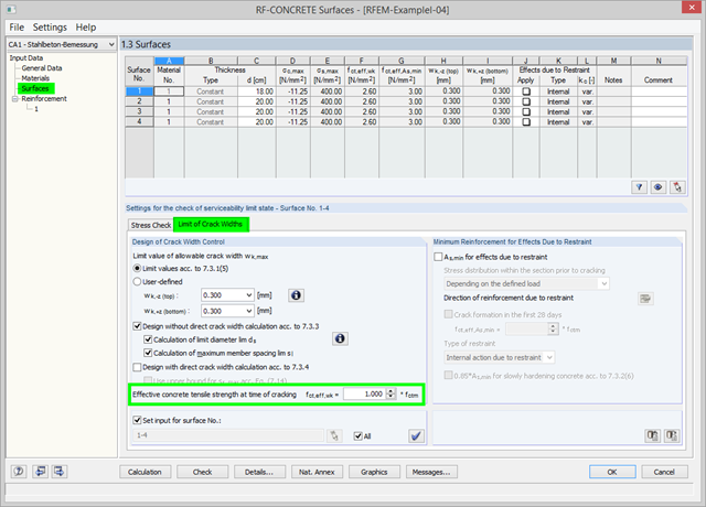
As of RFEM Version 5.06, there is the option in RF‑CONCRETE Surfaces to adjust the effective concrete tensile strength at the time of cracking. At the start of the SLS design, the program checks whether the internal forces can cause cracks in the concrete. For this, the effective concrete tensile strength at the time of cracking is applied. You can adjust the strength via the factor. The calculation details display the adjusted value.
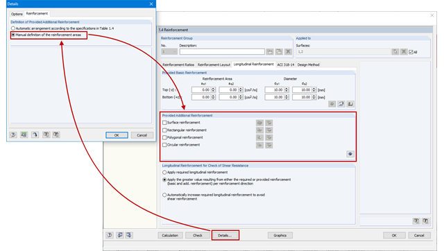
As an alternative to the conventional automatic arrangement of surface reinforcement in RF-CONCRETE Surfaces, it is also possible to set it according to the individual requirements. This is advantageous for the creation of reinforcement drawings, for example, as the reinforcement areas can be clearly defined and dimensioned.
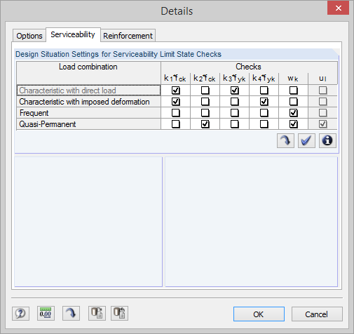
With program version 5.06, RF‑CONCRETE Surfaces and RF‑CONCRETE Members perform serviceability limit state designs automatically according to the design situation of the calculated load cases, load combinations, and result combinations.
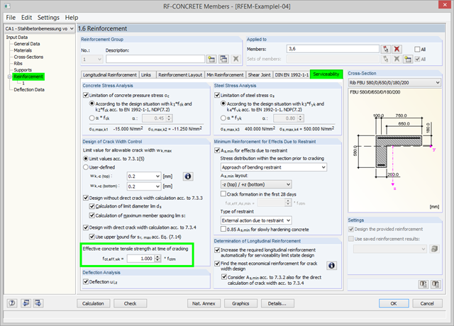
As of program version 5.06, you can use the option to adjust the effective concrete tensile strength fct,eff,wk at the time of cracking. At the start of the SLS design, the program checks whether the internal forces can cause cracks in the concrete. For this, the effective concrete tensile strength at the time of cracking is applied. You can adjust the strength via the factor. The calculation details display the adjusted value.
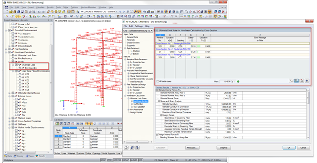
With RFEM 5.6.1103 and RSTAB 8.6.1103, there is an improved result output for the nonlinear calculation of reinforced concrete design in RF‑CONCRETE Members and CONCRETE. The new result windows include tables with a wide range of loading results; for example, governing load with the maximum ratio. In addition, you can now display the envelope results for the maximum ratio graphically.
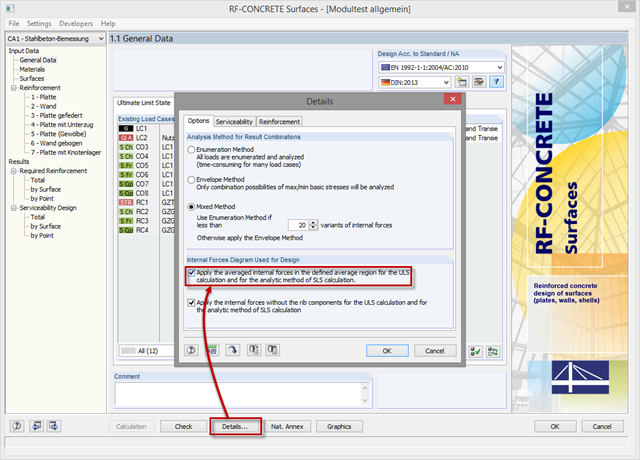
In order to use internal forces from average regions also for the design of concrete surfaces, you have to activate them in the module. For this, click the [Details] button in the "Tools" tab and select the option "Apply the averaged internal forces in the defined average region for the ULS calculation and for the analytic method of SLS calculation."
![Residual Stresses, Zero Line Position, and Tearing Depth when Cooling Pane on both Sides [2]](/en/webimage/009621/2419687/01-en-png-png.png?mw=640&hash=5e657e3feb5c1bb6d21727468dd85d91e1c9f29f)
Generally, avoiding cracking in concrete structures is neither possible nor necessary. However, cracking must be limited in a way so that the proper use, appearance, and durability of the structure are not affected. Therefore, limiting the crack width does not mean preventing from the crack formation, but restricting the crack width to harmless values.
![Parameters of Effective Slab Width (Figure 5.3 [1])](/en/webimage/009561/2419376/01-en-png.png?mw=640&hash=c76563b459152b19c98197ea6ba342be89d9a5bc)
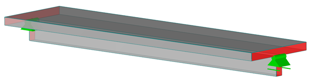
In the case of combined FEM structures (surface and member elements) as well as folded plate structures, it is possible to attribute a beam structure for the design on a member to a fictitious T-beam cross-section, whose geometry depends on the effective width. When using the "Rib" member type in RFEM, the stiffness is represented by a slab component (surface element) and a web component (member element). This approach has some design specifics that are explained in this article.
![Design Model for Bonded Joint Resistance According to [1]](/en/webimage/009526/2419234/01-en-png.png?mw=640&hash=c76563b459152b19c98197ea6ba342be89d9a5bc)
In the construction process, it is often necessary to fabricate the concrete elements in sections. A classic example of this production in sections is the use of prefabricated downstand beams, in which the slab is completed in the onsite concrete construction. By creating a new concrete area, interfaces may arise between the already hardened concrete and the fresh concrete. The transfer of the longitudinal shear forces arising between the partial cross-sections must be considered in the design.

According to Clause 7.3.2 (2), standard DIN EN 1992-1-1 requires: "In profiled cross‑sections like T‑beams and box girders, the minimum reinforcement should be determined for the individual parts of the section (webs, flanges)." In the case of a floor beam with a T‑section, the minimum reinforcement should be determined for both flanges and the web if the corresponding partial cross‑sections are in the tension area. Image 01 shows the division into partial cross-sections.
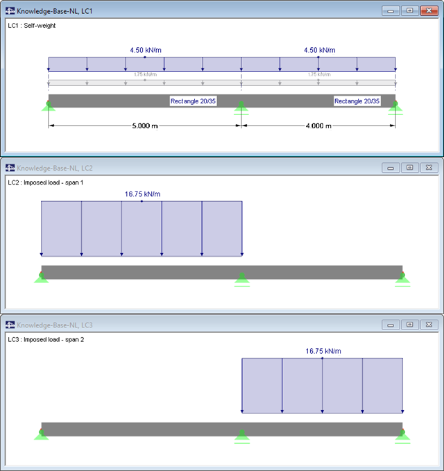
RFEM and the RF-CONCRETE add-on modules provide various options for the deformation analysis of a T-beam in the cracked state (state II). This technical article describes the calculation methods (C) and modeling options (M). Both the calculation methods and the modeling options are not limited to T-beams, but will only be explained using this system as an example.
![Tension Cover Line from [1]](/en/webimage/009390/2418541/01-en-png.png?mw=640&hash=c76563b459152b19c98197ea6ba342be89d9a5bc)
In the case of a large amount of reinforcement, it might be useful to grade the longitudinal reinforcement of a beam, which means: curtailment. The grading corresponds to the tensile force distribution. Using RF-CONCRETE Members and CONCRETE, you can specify the curtailment of the reinforcement, which is considered in the automatically proposed reinforcement for the longitudinal reinforcement. When determining this reinforcement proposal, it is necessary to ensure that the envelope of the acting tensile force can be absorbed.
When designing reinforced concrete components according to EN 1992‑1‑1 [1], nonlinear methods of determining internal forces for the ultimate and serviceability limit states are possible. In this case, the internal forces and deformations are determined with respect to their nonlinear behaviour. The analysis of stresses and strains in cracked state usually provides the deflections, which clearly exceed the linearly determined values.