Crack width w is defined as the width of the cracks on the component surface, as the crack width decreases with increasing distance from the surface. The allowable size of the crack width depends on the environmental conditions, the function of the structural component, and the corrosion susceptibility of the reinforcing steel [1].
Causes of Crack Formation Due to Early Restraint
An important effect in the crack formation is the so-called early restraint, where the most significant values generating the restraint are the temperature changes due to hydration heat formation, the concrete shrinkage and building ground motion. In the case of reinforced concrete structural components in particular, cracks in early‑age concrete usually occur a few days after the stripping. In the case of thick walls, the hydration heat formation can also lead to the development of internal stresses, which are caused by temperature differences over the cross-section and result in the shell cracks on the wall surface.
![Residual Stresses, Zero Line Position, and Tearing Depth when Cooling Pane on both Sides [2]](/en/webimage/009621/2419687/01-en-png-png.png)
The concrete that is up to three days old is referred to as a young concrete. After this time, the young concrete reaches a degree of hydration of 60 to 90%, depending on the cement type, the ambient temperature and the water-cement ratio. Young concrete is characterized by the following properties:
- strong heat development and thus heat exchange with the surroundings,
- large volume change due to the heat development,
- and rapid change of mechanical properties due to the gradual hydration.
During hydration heat formation, internal stress conditions occur especially in reinforced concrete structural components, which lead to compression stresses and tension stresses in the edge areas of the cross‑section. Based on the differences without the corresponding countermeasures, this stress condition leads to the formation of large cracks.
Countermeasures
Generally, it is possible to minimize or slow down the formation of restraint stresses by applying advanced concrete technology measures or appropriate curing, or arranging expansion joints. Since it is impossible to avoid crack formation completely, cracks must be limited and distributed by suitable reinforcement.
Determination of Minimum Reinforcement
In order to ensure the limitation of crack widths, it is necessary to create the minimum reinforcement for crack width control. Below, the calculation of the minimum reinforcement according to DIN EN 1992-1-1 is compared with the results of RF-CONCRETE Surfaces.
Initial values:
Wall thickness: h = 100 cm
Concrete cover: cnom = 40 mm for exposure class XC4
Concrete: C30/37
Reinforcing steel: B 500 S (A)
Allowable crack width: wk = 0.2 mm
Selected rebar diameter: ds = 14 mm
where
kc = 1.0 (pure tension)
k = 0.65 ∙ 0.8 = 0.52 (with modification for internal stresses)
fct,eff = 0.5 ∙ fctm = 1.45 N/mm²
act = h/2 ∙ b = 5,000 cm²/m
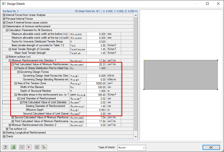
σs is defined using the limit diameter ds* as follows:
20.2 mm ≤ 28.0 mm
where
d = h - (cnom + ds / 2) = 95.3 cm
hcr = h = 100 cm
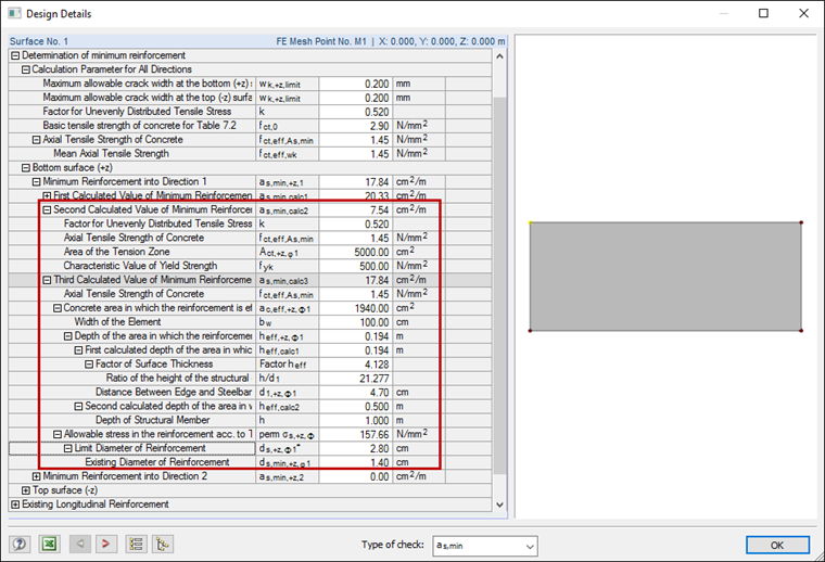
For thicker structural components, you can perform the calculation of the minimum reinforcement considering the effective edge zone Ac,eff, and in this case, the reinforcement should no longer be created, as it was determined in the previous calculation [3].
where
k = 0.52
fct,eff = 0.5 ∙ fctm = 1.45 N/mm²
ac,eff = hc,eff ∙ b = 19.4 cm ∙ 100 cm/m [according to Figure 7.1d)DE]
act = h / 2 ∙ b = 5,000 cm²/m
fyk = 500 N/mm²
σs is defined using the limit diameter ds* as follows: