Activating the Manual Definition of Reinforcement Areas
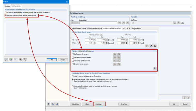
You can switch to the manual definition of reinforcement areas by clicking the [Details...] button in the RF‑CONCRETE Surfaces add‑on module. In the "Reinforcement" tab, select the "Manual definition of the reinforcement areas" option.
The "Provided Reinforcement" section appears subsequently instead of "Additional Reinforcement for Serviceability State Design" in Window 1.4 Reinforcement.
Entering a Reinforcement
The input of the reinforcement is described using the example of the rectangular reinforcement. The other reinforcement types can be created in the same way. The surface reinforcement always refers to the total area, while the rectangular, polygonal, and circular reinforcement usually apply to partial surfaces.
After activating the rectangular reinforcement by selecting the corresponding option, you can click the [Apply free rectangular reinforcement] button to open the "New Rectangular Reinforcement" dialog box.
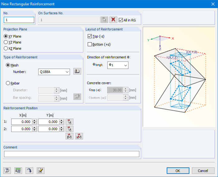
The reinforcement properties and layouts are defined in this dialog box. Among other things, you can also define on which surfaces the reinforcement should apply. If the "All in RG" option is selected, the reinforcement is applied to all surfaces. This option is especially useful when there are several slabs with the same geometry and loading.
In the "Type of Reinforcement" section, you can select whether mesh or rebar reinforcement should be created.
The "Layout of Reinforcement" section includes options for specifying the slab side as well as the direction of surface reinforcement. You can optionally select a concrete cover. In this case, the data are imported from the "Reinforcement Layout" tab.
When defining the "Reinforcement Position" using the coordinates, you should make sure that the position corresponds to the FE mesh. Once the rectangle surrounds the center point of the element, the reinforcement is created for the entire element.
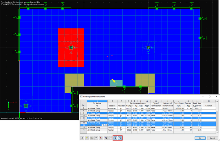
The values of the reinforcement surfaces lying next to each other will be added to the relevant element. As soon as the reinforcement is defined, you can open the corresponding table by clicking the [Edit...] button. This table provides an overview of the defined reinforcement surfaces that can be edited further.
![[Edit] Button](/en/webimage/009727/2420111/03-en-png-png.png)
The table includes copying and filtering functions to manage the already entered reinforcement easily and clearly. You can always monitor the editing process precisely through simultaneous synchronization by only showing the selected reinforcement.
Checking the Reinforcement Covering
After the reinforcement has been entered successfully, you can check the covering of the required reinforcement in the Results navigator. On one hand, the "Not Covered Reinforcement" option allows you to quickly check in which areas insufficient reinforcement has been defined; on the other hand, you can use the "A-s,req/A-s,prov" function to see which part of the required reinforcement is already covered.
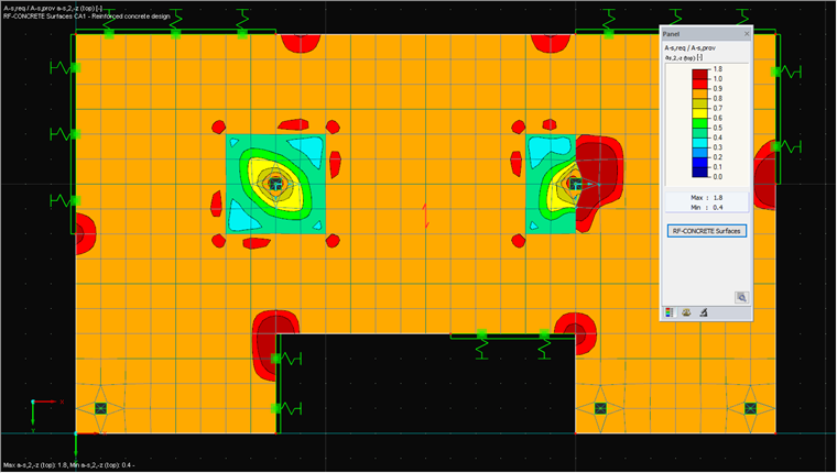
The dark red areas in Figure 5 are not reinforced sufficiently yet.
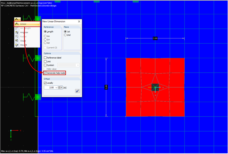
Dimensioning Free Reinforcement
Free reinforcement can be dimensioned easily by using the "Linear Dimension" function. In the corresponding dialog box, it is necessary to select the "Generate help node" option, otherwise the free reinforcement cannot be captured. Now you can create nodes on the relevant points, which will then be dimensioned.