Curtailment of Longitudinal Tension Reinforcement
The design of the curtailment of the longitudinal tension reinforcement ensures that the envelope of the acting tensile force FSd can be absorbed by the provided reinforcement. 9.2.1.3(2) of EN 1992‑1‑1 [1] also requires considering the additional tensile force ΔFtd due to the shear force. For structural components with shear reinforcement, this additional tensile force ΔFtd can be calculated according to 6.2.3 (7) of EN 1992‑1‑1 [1]. The tensile force FSd is calculated from the following equation:
For structural components without shear reinforcement, the tensile force component ΔFtd may be taken into account by shifting the tensile force curve by the shift rule al = d in the unfavorable direction. This approach may also be used as an alternative to the approach for structural components with shear reinforcement mentioned above. In this case, this "shift rule" is determined according to the following formula:
![Tension Cover Line from [1]](/en/webimage/009390/2418541/01-en-png.png?mw=760&hash=7ec548270c812e4679005b311ca774da4860d51a)
The resistant tensile force FRs of the provided reinforcement is determined within the anchorage lengths lbd.
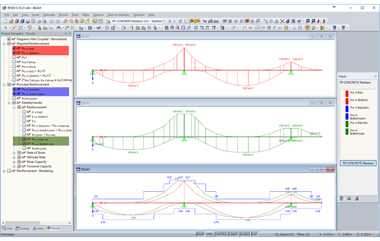
Graphical Display of Reinforcement Covering Line / Curtailment of Longitudinal Reinforcement
When the tensile force of the curtailment of longitudinal reinforcement is divided by the design stiffness fyd of the reinforcing steel, a reinforcement covering line is obtained. In RF-CONCRETE Members and CONCRETE, the distribution of the required tension reinforcement As (first result diagram in Image 02) is shifted by the shift rule al in order to obtain the envelope of the required reinforcement (second result diagram in Image 02). You can display these shifted required reinforcement envelopes graphically by selecting "Detailed results" under "Provided Reinforcement" in the Results Navigator (see Image 02).
If the envelope of the required reinforcement (red), the shifted envelope of the required reinforcement (green), and the provided reinforcement (blue) are shown together graphically, a reinforcement covering line is obtained (third result diagram in Image 02) that corresponds to the curtailment of longitudinal reinforcement in Fig. 9.2 of EN 1992‑1‑1.