


One of the previous articles explains the general methods for the calculation and modeling of downstand beams, ribs, and T‑beams in the cracked state.
This article describes the design process of a continuous beam made of reinforced concrete. The calculation can be carried out in the CONCRETE and RF‑CONCRETE Members add‑on modules in combination with the licenses for EC2 and RF‑CONCRETE NL.
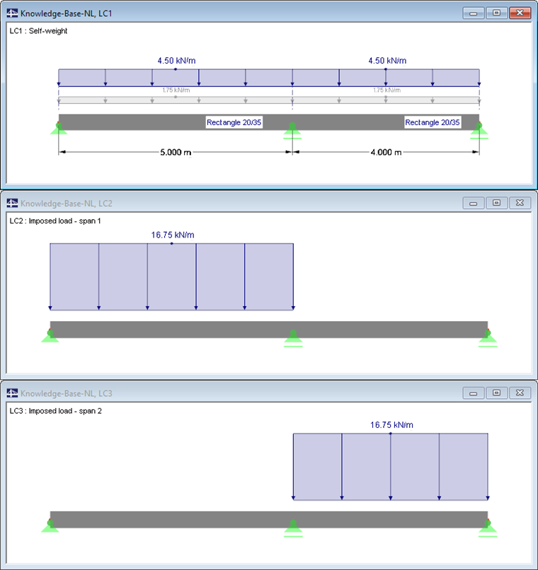
System and Loading
A continuous beam consists of a rectangular cross‑section of 20/35 cm and concrete class C30/37.
The permanent loads and traffic loads are organized in three load cases. To determine the design combinations according to EN 1990, the automatic combinatorics for the ultimate limit state and the serviceability limit state (usual design situation) of RFEM/RSTAB are used.
Linear Calculation of Reinforcement in ULS
First, the reinforcement is determined for the ultimate limit state. The calculation is performed, taking into account the moment redistribution and reduction for the internal forces of the result combination RC1. Furthermore, the following reinforcement parameters are specified:
- Reinforcement diameter of 16 mm
- Curtailment of reinforcement for three areas
- Concrete cover of 30 mm
- Minimum reinforcement of 2 Ø 12 for the upper and bottom positions
- Secondary reinforcement for the maximum reinforcement distance of 15&bsp;cm with Ø 12
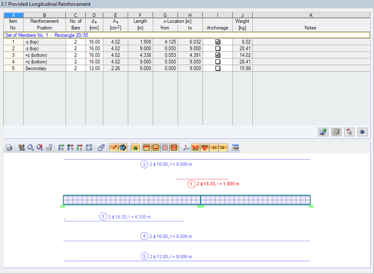
Based on these entries, the program determines a reinforcement concept according to the linear-elastic approach. In Window 3.1, it is possible to check the reinforcement, which is the basis for the nonlinear analysis.
Nonlinear Calculation of Crack Widths and Deformations in SLS
The nonlinear calculation of the serviceability limit state is performed for the load combinations LC6 to LC8 (result combinations do not allow for any clear stress-strain relations). In the nonlinear analysis, the tension stiffening effects should be integrated. For this, the method with the modified characteristic curve for steel according to [2] is applied.
![Window "1.1 General Data" for Serviceability Limit State with Settings for Nonlinear Calculation According to [2]](/en/webimage/009376/2418464/03-en-png.png?mw=760&hash=1064f34dc0c9674b34f8f615fdd341dda4cb6fd1)
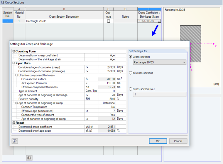
In addition, the creep and shrinkage effects are considered. These can be set in Window 1.3.
Results
A physical and geometric nonlinear calculation is performed. The iteration of the strain state takes place at the cross-sectional level. Based on the distribution of internal forces within the iteration cycle, new current strain-stress states are always calculated. The convergence is achieved when the state of equilibrium is set.
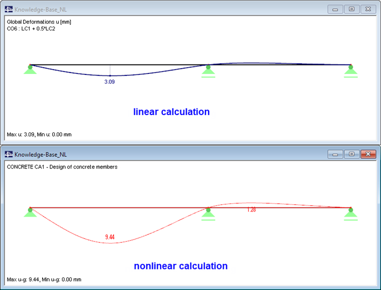
As expected, the maximum deformations occur in Field 1 for the loading of LC6 (LC1 + 0.5 ∙ LC2). The crack widths are small.
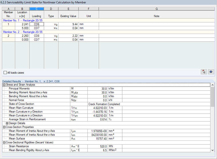
The deformation resulting from the nonlinear calculation with regard to the creep effect is significantly greater than the deformation from the pure linear elastic calculation without the creep effect. This is obvious when comparing the deformations.
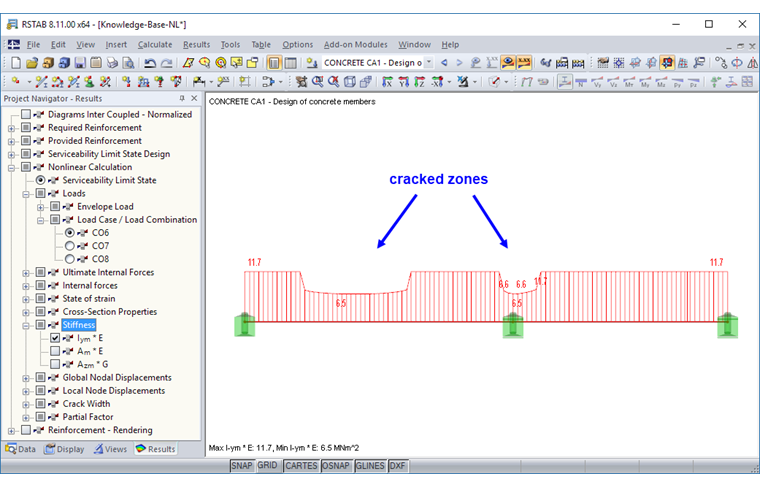
The stiffness diagram shows that a large area of Field 1 is cracked in the serviceability state.
Conclusion
In comparison with the linear-elastic calculation of reinforced concrete components, the nonlinear stiffness and stress analysis provides deformation values that can be considerably higher when considering the crack formation. This effect can be resolved by using the nonlinear analysis methods implemented in the add-on modules for structural analysis and design of reinforced concrete structures by Dlubal Software. It is also possible to consider the creep and shrinkage effects here.