493 Results
View Results:
Sort by:

Lateral-Torsional Buckling (LTB) is a phenomenon that occurs when a beam or structural member is subjected to bending and the compression flange is not sufficiently supported laterally. This leads to a combination of lateral displacement and twisting. It is a critical consideration in the design of structural elements, especially in slender beams and girders.

This article describes and explains the influence of bending stiffness of cables on their internal forces. Furthermore, the text provides information on how this influence can be reduced.

The ASCE 7-22 Standard [1], Sect. 12.9.1.6 specifies when P-delta effects should be considered when running a modal response spectrum analysis for seismic design. In the NBC 2020 [2], Sent. 4.1.8.3.8.c gives only a short requirement that sway effects due to the interaction of gravity loads with the deformed structure should be considered. Therefore, there may be situations where second-order effects, also known as P-delta, must be considered when carrying out a seismic analysis.

In this article, the calculation of a timber panel wall with the beam panel thickness type is compared with a manual calculation.

Using the Timber Design add-on, timber column design is possible according to the 2018 NDS standard ASD method. Accurately calculating timber member compressive capacity and adjustment factors is important for safety considerations and design. The following article will verify the maximum critical buckling strength calculated by the Timber Design add-on using step-by-step analytical equations as per the NDS 2018 standard including the compressive adjustment factors, adjusted compressive design value, and final design ratio.

In this article, you will learn how to model and design cable structures in RFEM 6 or RSTAB 9.
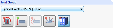
Starting with program version X.06, joint groups are clearly identified in RF‑/JOINTS.

The three types of moment frames (Ordinary, Intermediate, Special) are available in the Steel Design add-on of RFEM 6. The seismic design result according to AISC 341-22 is categorized into two sections: member requirements and connection requirements.
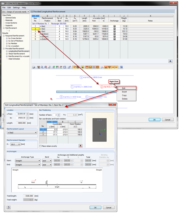
With the introduction of OSG graphics for the representation of design reinforcement in RF‑CONCRETE Members and CONCRETE, you can also select the reinforcement position directly in the graphic. Right-click the mouse to open the context menu where you can edit, copy, or delete the selected reinforcement position.
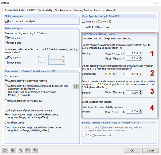
For situations where no design is available, RF-/STEEL EC3 provides the option to neglect the respective internal forces. Examples of such situations are: bending and compression on angle sections, multi-axial bending for the design according to the General Method, torsion.
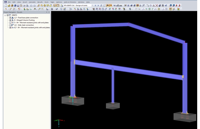
The updated Results Navigator of RF‑JOINTS allows you to display the results of different module cases simultaneously. Thus, you can display all column base designs at the same time in order to perform collision checks of the foundations, for example.

Moment frame design according to AISC 341-16 is now possible in the Steel Design add-on of RFEM 6. The seismic design result is categorized into two sections: member requirements and connection requirements. This article covers the required strength of the connection. An example comparison of the results between RFEM and the AISC Seismic Design Manual [2] is presented.
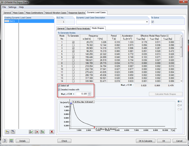
With the latest version of RF‑/DYNAM Pro, you can exclude the mode shapes from the seismic design. In most standards, there are provisions to exclude the effective modal mass factors that are too small. The "Mode Shapes" tab offers the option to specify the factor and to disregard the mode shapes automatically.

The three types of moment frames (Ordinary, Intermediate, Special) are available in the Steel Design add-on of RFEM 6. The seismic design result according to AISC 341-16 is categorized into two sections: member requirements and connection requirements.
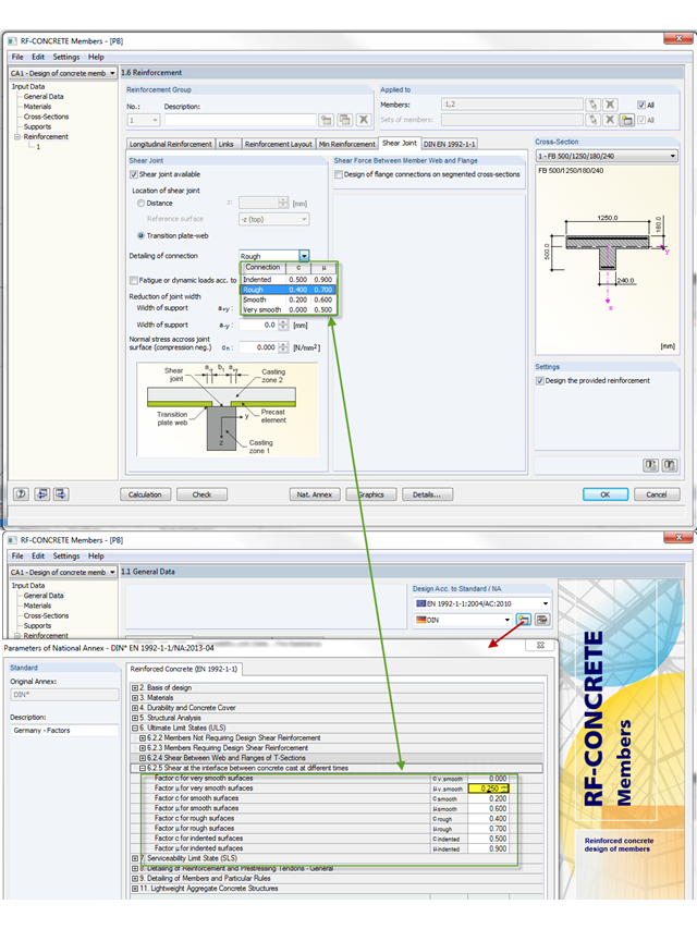
The shear resistance design value of a joint depends mainly on the formation or the roughness of the connection. When determining the ultimate limit state, this is considered by the factors µ (friction) and c (adhesion percentage of the contact area of the composite concrete).
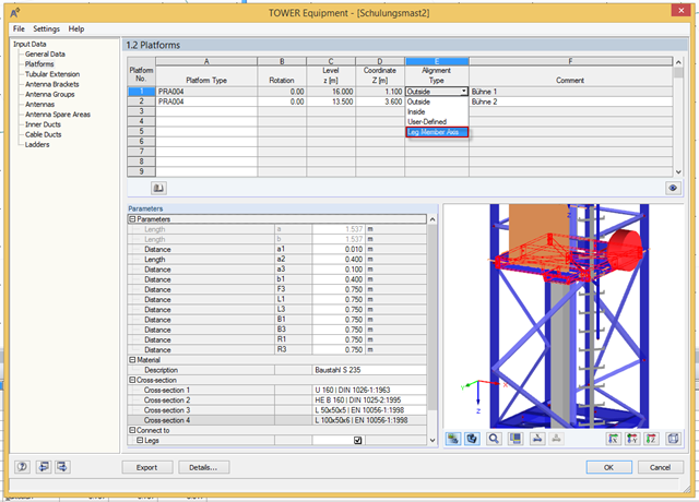
Platforms can be connected directly to leg members using the new "Leg Member Axis" option. Thus, it is no longer necessary to define the platform width or coupling member.
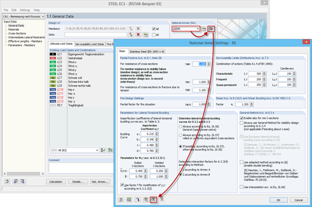
If you want to design structural components in an RFEM or RSTAB add‑on module, several National Annexes are available in some add‑on modules. In the case of structures that are to be analyzed mainly according to a specific National Annex, the add‑on modules provide the option to set a default value. Thus, it is unnecessary to select the NA again for each new model.

RF‑/FOUNDATION Pro introduced the geotechnical design of single foundations according to EN 1997‑1 in RFEM 5 and RSTAB 8. Depending on the National Annex preset in the add‑on module, you can determine the bearing resistance using Approach 2 or 3 in compliance with EN 1997‑1 up to Version x.04.0108.
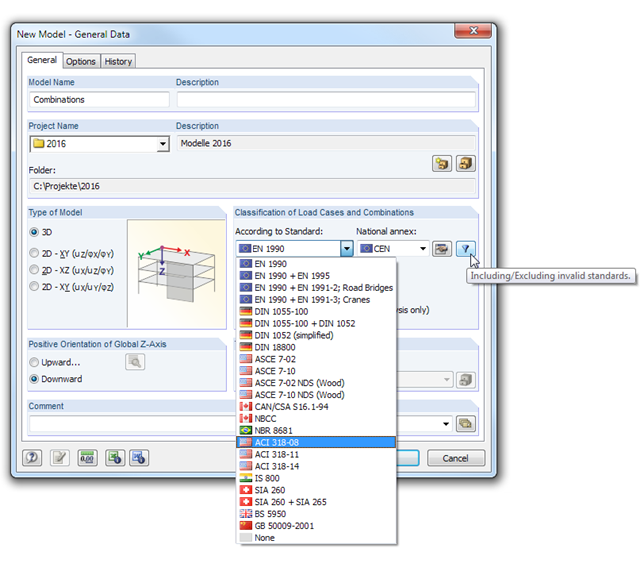
In RFEM and RSTAB, load cases can be combined automatically using combination coefficients (partial safety factors) in order to determine the required design situations.

This article explains how the calculation in the initial stiffness analysis in Steel Joints works.