38 Results
View Results:
Sort by:

The data exchange between RFEM 6 and Allplan can be done using various file formats. This article describes the data exchange of a determined surface reinforcement using the ASF interface. This allows you to display the RFEM reinforcement values as level curves or colored reinforcement images in Allplan.

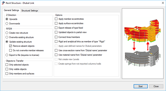
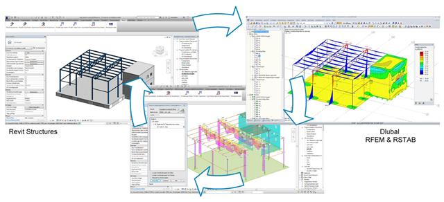
As for the previous generations of Dlubal programs, an integrated interface with Autodesk Revit is now also available for RFEM 6 and RSTAB 9. This article will provide some general information about the interface as well as the Dlubal-relevant structural objects and parameters in Revit.

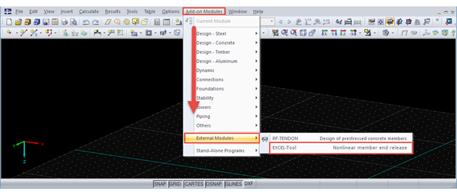
Spreadsheet programs like MS EXCEL are very popular with engineers because they allow you to simply automatize your calculations and quickly output the results. Therefore, combining MS EXCEL used as a graphical interface with Dlubal's WebService API is an obvious choice. By using the free xlwings library for Python, you can control EXCEL, and read and write values. The functionality is described in the following, using an example.
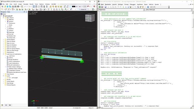
Webservice is a communication between machines and programs. This communication is provided via the network and can, therefore, be used by any program that can send and receive strings via the HTTP protocol. RFEM 6 and RSTAB 9 provide an interface based on these cross-platform webservices. This tutorial shows the basics using the VBA programming language.

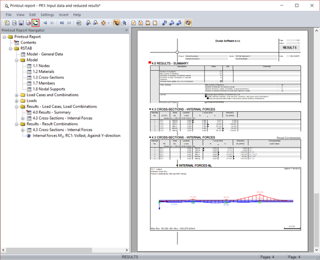
The individually defined printout reports in an RFEM or RSTAB model can be displayed in different ways.
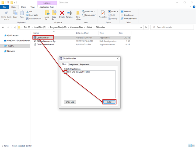
The interface to Autodesk Revit is installed automatically during the installation of RFEM 5 or RSTAB 8. Subsequent installation of the plug‑in is possible through the execution of Revit-Installer.exe.

In RF-/STEEL EC3, you can optimize a cross-section automatically within the design. To do this, select the corresponding cross-section in Table 1.3 or define variable parameters for a welded cross-section.
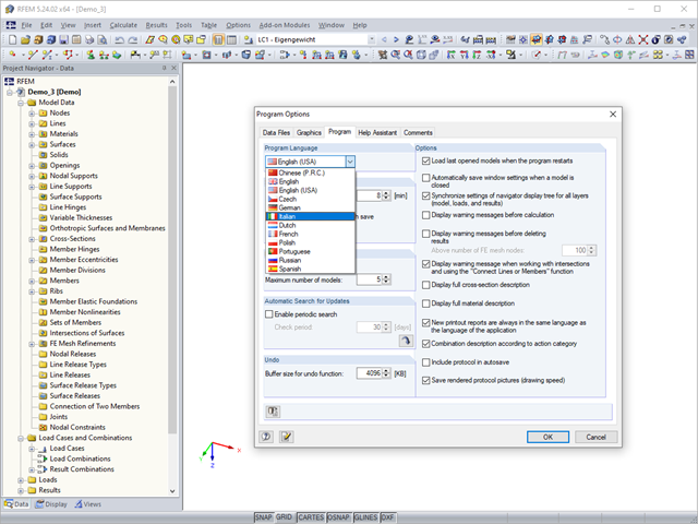
RFEM, RSTAB, and SHAPE-THIN are localized in eleven languages. All languages are available at no extra charge. The language of the program interface can be defined in the menu "Options" → "Program Options".
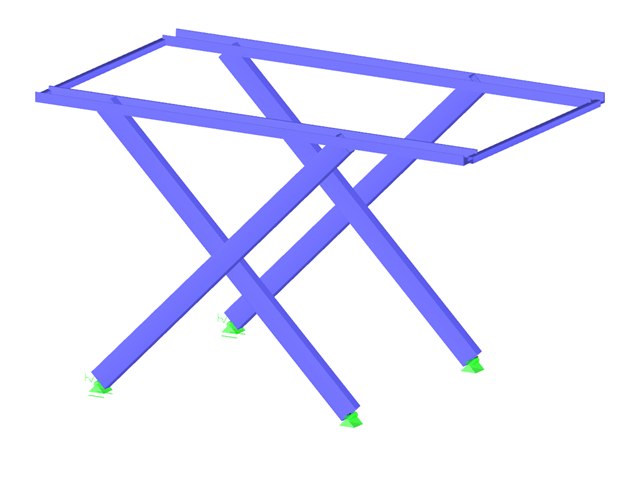
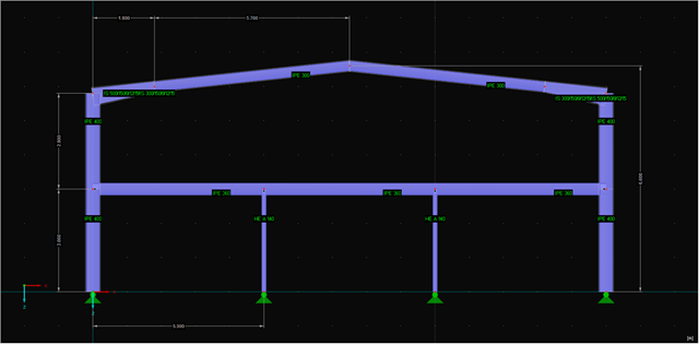
It is necessary to design some structures in different configurations. It may be that an aerial work platform must be analyzed in its position on the ground as well as in the middle and in the extended position. Since such tasks require the creation of several models, which are almost identical, updating all the models with just one mouse click is a considerable relief.

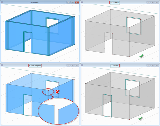
In RFEM and RSTAB, you can use many interfaces to simplify the modeling of your structure. From background layers, to the import of IFC objects that can be converted into members or surfaces, to the import of the entire structural system from Revit or Tekla. Regardless of the performance of the selected interface, further utilization also depends on the accuracy of the imported data.
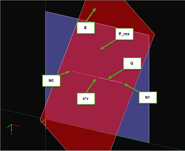
If you read out the results of a surface by means of the COM interface, you get a one-dimensional field with all results at the FE nodes or grid points. To get the results on the edge of a surface or along a line within the surfaces, you have to filter out the results in the area of the line. The following article describes a function for this step.
.png?mw=640&hash=1be9a846b1f57190540c7fc7f46f44cd40ab7029)
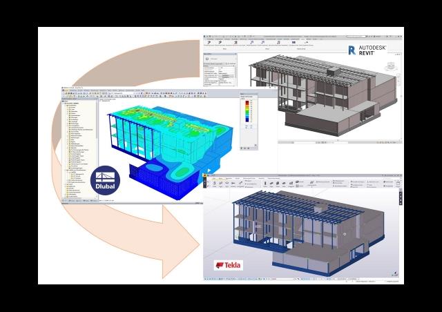
The calculation of structures based on digital twins is becoming an everyday task in the engineering office. If a digital building model already exists, you want to continue to use the information contained in it as seamlessly as possible. This states extensive requirements with regard to modeling and interfaces for BIM-compatible structural analysis software.
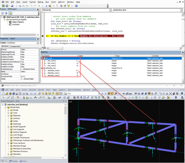
When editing elements via the COM interface, selecting elements is often a problem because it cannot be carried out visually via the work window. The selection can be particularly difficult for models that have been created via the program interface and are then to be modified using a separate program. Apart from the exception, when the selection was made previously via RFEM, there are several alternatives for programming.
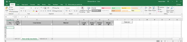
The parts lists give information about which and how many parts are necessary for creating a building. They form the basis for identifying the needs and purchasing the components. Parts lists can be created in design modules, such as RF‑/STEEL EC3, RF‑/TIMBER Pro, and so on. Furthermore, a customized parts list can be created with the RF-COM/RS-COM interface.
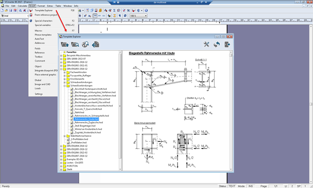
An interface can be used to export the RFEM/RSTAB printout report to VCmaster and continue editing there. VCmaster is a word processing program for engineers.
RF-COM/RS-COM is a programmable interface that allows the user to expand the main programs RFEM and RSTAB with customized input macros or post‑processing programs. A tool to copy and move selected guidelines in RFEM will be developed in this article. It is also possible to copy or move the guidelines to another work plane. VBA in Excel will be used as the programming environment.
This article discusses the most common BIM interfaces. Adjustments are often necessary during the transition to the structural branch-specific model. The tasks that arise and the tools to address them successfully and quickly are presented.
Printout reports created in RFEM and RSTAB can be transferred to VCmaster using a direct interface and further processed there. VCmaster (formerly BauText) is a word processing program for engineers. Calculations, drawings, photos, and documents from various sources can be easily compiled, managed and used again with VCmaster.
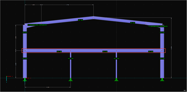
Part 4.1 of this article series describes the connection of the RF‑/STEEL EC3 add‑on module; the members and load combinations to be designed were already defined. This section will focus on the optimization of cross‑sections in the module and the transfer to RFEM. The elements already explained in the previous parts are not described again.
Sections 4.1 and 4.2 of this article series describe the optimization of a frame using the RF‑/STEEL EC3 add-on module. The fifth section explains how to link the module and get the relevant members. The elements already explained in the previous sections will not be described again.
BIM is often used when it comes to data management in civil engineering. The individual disciplines of architecture, structural design, construction, and structural monitoring are coming closer together. Building Information Modeling makes this possible.. Dlubal Software provides a wide range of formats for data exchange. The following article explains the details of the interface with Autodesk Revit and, in particular, the export settings.
![Design Model for Bonded Joint Resistance According to [1]](/en/webimage/009526/2419234/01-en-png.png?mw=640&hash=c76563b459152b19c98197ea6ba342be89d9a5bc)
In the construction process, it is often necessary to fabricate the concrete elements in sections. A classic example of this production in sections is the use of prefabricated downstand beams, in which the slab is completed in the onsite concrete construction. By creating a new concrete area, interfaces may arise between the already hardened concrete and the fresh concrete. The transfer of the longitudinal shear forces arising between the partial cross-sections must be considered in the design.
Part 2.2 of the article series about the COM interface describes creating and modifying nodal supports, loads, load cases, load combinations, and result combinations on an example of a member. The fourth part explains creating individual tools.
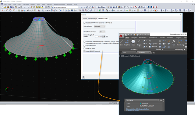
The DXF interface in RFEM now exports a 3DFACE element in the DXF file for each FE mesh cell of the exported structure. The 3DFACE element is detected by AutoCAD during import, for example, and can be displayed as a surface in the graphic. Different visual styles help display the 3DFACE surfaces in a desired view.

With RFEM 5.06 and RSTAB 8.06, the examples and help files for programming the COM interface are not only available on the Internet, they are also included in the installation. To find them, look for the "SDK" folder in the project directory (usually C:\Users\Public\Documents\Dlubal).
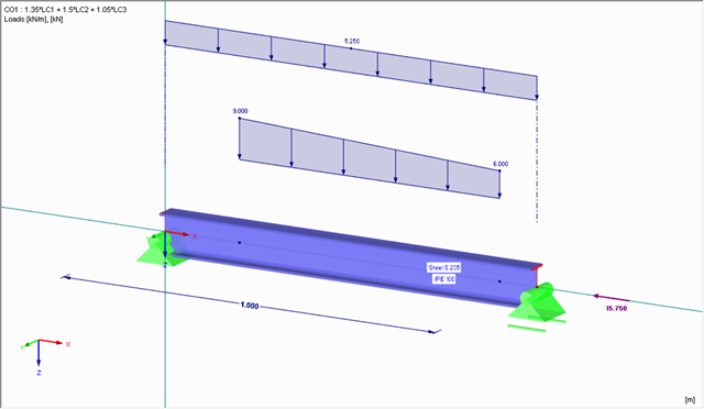
Part 2.1 of the article series about the COM interface described creating and modifying elements on an example of a member. In the third part, these core elements are used again to create nodal supports, loads, load combinations, and result combinations. Thus, the model created in the second part will be extended. Therefore, the elements explained in Part 1 and Part 2.1 are not described again.
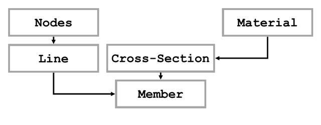
The first part of the article series about the COM interface described opening and creating a model in RFEM. The second part explains creating and modifying elements on an example of a member. The elements described in Part 1 will not be explained again here.
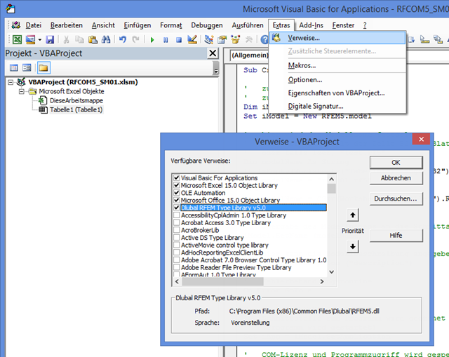
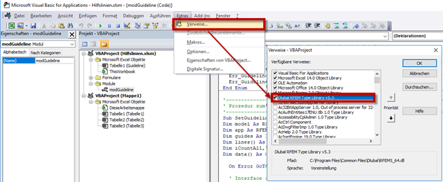
The first part of the post about the COM interface describes opening and closing RFEM. VBA programming language is used in Excel; however, the program sequence is the same as for programming with C#. First, it is necessary to add the corresponding reference in VBA to recognize the commands for the interface. The image on the left shows an example of RFEM 5.
In his bachelor's thesis, Jonas Mösch analyzes the open and closed interfaces in BIM-based structural design. The theoretical section covers the definition of the term "Building Information Modeling".
In RFEM and RSTAB, several interfaces are available. The DSTV interface (*.stp) is the most convenient for importing beam structures, since supports, hinges, loads, and load combinations are also transferred, in addition to the general topology.