44 Results
View Results:
Sort by:

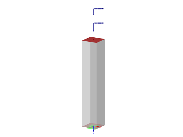
The goal of using the RFEM 6 and Blender with the Bullet Constraints Builder add-on is to obtain a graphical representation of the collapse of a model based on real data of physical properties. RFEM 6 serves as the source of geometry and data for the simulation. This is another example of why it is important to maintain our programs as so-called BIM Open, in order to achieve collaboration across software domains.

A standard scenario in timber member construction is the ability to connect smaller members by means of bearing on a larger girder member. Additionally, member end conditions may include a similar situation where the beam is bearing on a support type. In either scenario, the beam must be designed to consider the bearing capacity perpendicular to the grain according to NDS 2018 Sec. 3.10.2 and CSA O86:19 Clauses 6.5.6 and 7.5.9. In general structural design software, it is typically not possible to carry out this full design check, as the bearing area is unknown. However, in the new generation RFEM 6 and Timber Design add-on, the added 'design supports' feature now allows users to comply with the NDS and CSA bearing perpendicular to the grain design checks.

With the release of the structural analysis programs RFEM 6, RSTAB 9, RSECTION 1, and RWIND 2, Dlubal Software introduces a new generation of structural analysis programs. True to the motto "Structural analysis that is fun ...", the program provides users with universal tools with which they can meet all the requirements in structural engineering. Find out more about the latest developments at Dlubal Software in this article.

The new RFEM software generation provides the option to perform stability design of tapered timber members in line with the equivalent member method. According to this method, the design can be performed if the guidelines of DIN 1052, Section E8.4.2 for variable cross-sections are met. In various technical literature, this method is also adopted for Eurocode 5. This article demonstrates how to use the equivalent member method for a tapered roof girder.

The calculation of complex structures by means of finite element analysis software is generally performed on the entire model. However, the construction of such structures is a process carried out in multiple stages where the final state of the building is achieved by combining the separate structural parts. To avoid errors in the calculation of overall models, the influence of the construction process must be considered. In RFEM 6, this is possible using the Construction Stages Analysis (CSA) add-on.

The new generation of RFEM software is an intuitive, powerful, and easy-to-handle 3D FEA program that meets all the latest demands in modeling, calculation, and structural design. The modern design concept, as well as the introduction of new features, make the program even more innovative and user-friendly. The main differences between RFEM 6 and its previous version, RFEM 5, are discussed in the following text.
This article deals with rectilinear elements of which the cross-section is subjected to axial compressive force. The purpose of this article is to show how very many parameters defined in the Eurocodes for concrete column calculation are considered in the RFEM 5 structural analysis software.
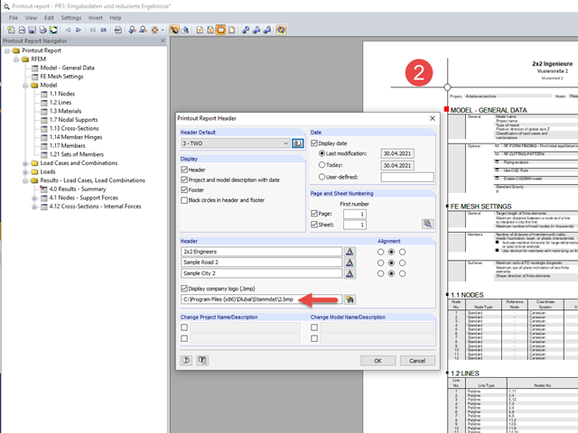
All Dlubal Software programs have access to the printout report environment.
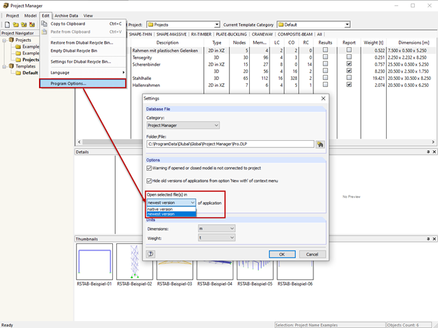
The network-capable Project Manager controls the projects of all Dlubal Software applications in one central location.

In the age of BIM, data exchange between the various disciplines of structural engineering is becoming increasingly important. Since each software has its own specifications with regard to the description of cross-sections and materials, RFEM and RSTAB offer a conversion table (mapping file).