- Full integration in RFEM/RSTAB including import of all relevant internal forces
- Intelligent presetting of flexural buckling-specific design parameters
- Automatic determination of the distribution of internal forces and classification according to DIN 18800, Part 2
- Optional import of buckling lengths from the RF-STABILITY/RSBUCK add-on module. For this, a comfortable graphical selection of the relevant buckling mode is possible
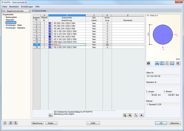
- Optimizing Cross-Sections
- Optional calculation according to both design methods of DIN 18800, Part 2
- Automatic determination of the most unfavorable design location, also for tapered members
- Check of c/t-limit values according to DIN 18800, Part 1
- Design of any thin-walled RFEM/RSTAB or SHAPE-THIN section for compression and bending without interaction according to the elastic-plastic method
- Design of I-shaped rolled and welded sections, I-like sections, box sections, and pipes subjected to bending and compression with iteration according to the elastic-plastic method
- Clearly arranged, comprehensible design checks with all intermediate values in the short and long forms
- Parts list of members and sets of members
- Direct export of all results to MS Excel
- A manual with manually calculated examples
It is possible to perform the following designs:
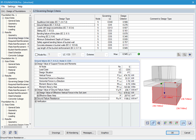
- Equilibrium limit state design
- Uplift limit state design
- Ground failure (soil contact pressure) design
- Strong eccentric loads design
- Design of foundation torsion and limitation of gaping joint
- Sliding design
- Settlement calculation
- Bending failure design of the plate and bucket
- Punching shear design
Foundation and bucket dimensions can be user-defined or determined by the module. You can edit the determined reinforcement manually. In this case, the designs are updated automatically.
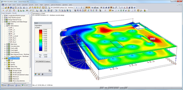
After the calculation, the module shows clearly arranged tables listing the results of the nonlinear calculation. All intermediate values are included in a comprehensible manner. Graphical representation of design ratios, deformations, concrete and reinforcing steel stresses, crack widths, crack depths, and crack spacing in RFEM facilitates a quick overview of critical or cracked areas.
Error messages or remarks concerning the calculation help you find design problems. Since the design results are displayed by surface or by point including all intermediate results, you can retrace all details of the calculation.
Due to the optional export of input or result tables to MS Excel, the data remain available for further use in other programs. The complete integration of results in the RFEM printout report guarantees verifiable structural design.
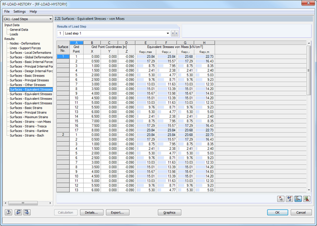
After the calculation, you can evaluate the results of the individual load steps directly in the module windows or graphically in a structural model.
The results include, for example, deformations, stresses, and internal forces of surfaces, as well as deformations and stresses of solids. It is possible to export the result combinations for each load step to RFEM. You can use these enveloping combinations for further designs in the other RFEM add-on modules.
All input data and results of the add-on module are part of the global RFEM printout report.
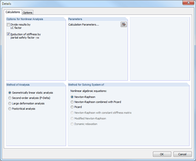
The calculation is performed successively for each load step. Permanent (plastic) deformations of previous load steps are considered when calculating further load steps. This way, it is also possible to perform a calculation with a structure relief.
The loads of the individual steps are added up (depending on the signs) throughout the calculation process. You can freely select the method of analysis (linear static, second-order, large deformation, and postcritical analysis). Furthermore, the module manages the global calculation settings.
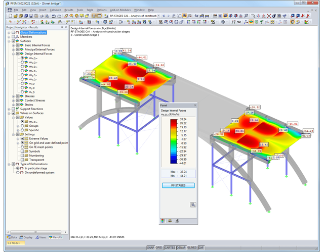
After the calculation, it is possible to evaluate the results of each construction stage directly in the module window or graphically in the RFEM/RSTAB model. In this case, you can export the results to RFEM/RSTAB.
The module creates result cases of each construction stage as well as an 'envelope' combination including the maximum and minimum values of all construction stages. You can use the result cases and the enveloping combination for further calculations in various RFEM/RSTAB add-on modules.
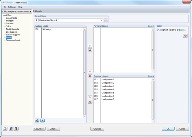
After creating the entire structure in RFEM/RSTAB, the individual structural components as well as load cases and combinations are assigned to the corresponding construction stages. For each construction stage, you can modify for example release definitions of members and supports.
Thus, it is possible to model structural modifications, such as those that occur when bridge girders are successively grouted or when columns are settled. The load cases and load combinations already created in RFEM/RSTAB are divided into "Permanent Loading" and "Temporary Loading" in the add-on module.
The defined temporary loads are superimposed by permanent loads. This way, it is possible to determine the maximum internal forces of different crane positions or to consider temporary mounting loads available only in one construction stage.
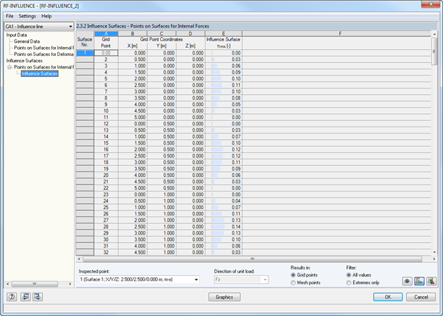
After defining the points to be analyzed, the module generates influence lines and surfaces. Then, all result diagrams are available in result windows sorted by points and unit loads applied on members, surfaces, and supports.
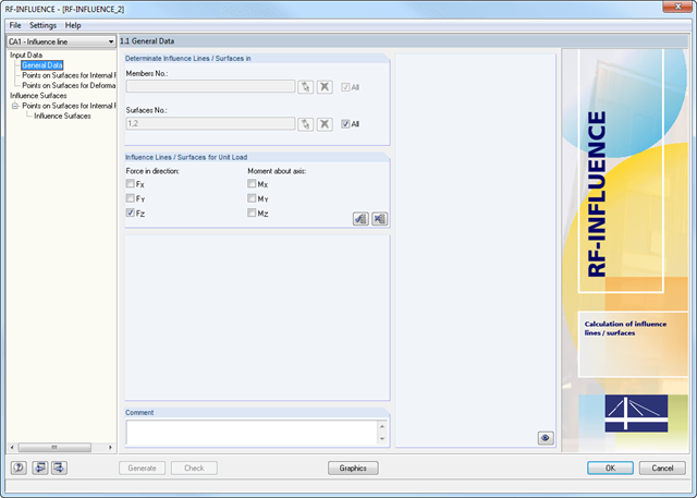
Member and surface models created in RFEM are analyzed at a particular point by applying a unit load with the previously defined load magnitude and direction. The module determines the way the unit load affects the internal forces at the inspected point.
This simulation is represented graphically by an influence line or influence surface resulting from the load magnitude of the force or moment at the inspected model point. The graphical representation can be used for further analyses or to check the behavior of the model.
The RF-INFLUENCE add-on module determines the influence lines and surfaces of models containing beams and surfaces.
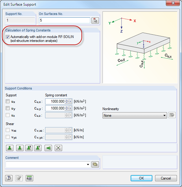
Elastic foundation coefficients are calculated according to the non-linear iterative method. The module determines elastic foundation coefficients for each individual element. They are dependent on the deformation.
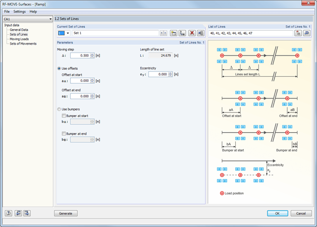
Surfaces with moving loads are selected graphically in the RFEM model. You can apply loads with several different sets of movement on one surface at the same time.
The 'lane' is defined by means of line sets. You can select them graphically in the model. In addition, you can enter the increment of the individual load steps. Several load types are available; for example, single, linear, rectangular, circular, and various axle loads. They can be applied in local and in global directions.
The different loads are summarized in load models. The module assigns defined load models to the sets of lines and creates individual load cases based on these data.
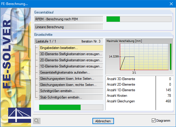
If the results of the designed actions are not available, RF-/DEFORM automatically starts the RFEM/RSTAB calculation in order to determine the deformations. The settings of the calculation parameters defined in RFEM/RSTAB are used.
Subsequently, the RF-/DEFORM add-on module determines the relative deformations of the designed members and sets of members.
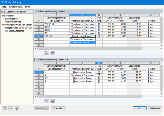
Design-relevant data are entered in two separate windows. Since the RF-/DEFORM module is very clearly arranged, working in it is very easy.
First of all, it is necessary to define the actions to be designed. Then, you can select the members and sets of members manually or graphically and assign the respective allowable limit deformations.
The deformations correspond to deformed member ends or an undeformed system.
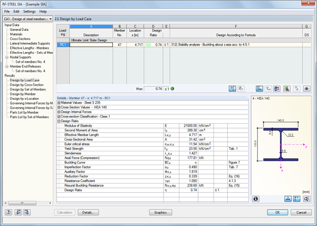
For reasons of result evaluation, clearly arranged result tables are available. The first window shows the maximum design ratios including the corresponding design of each designed load case, load combination, or result combination.
The other result windows list all detailed results sorted by specific subject in extendable tree menus. All intermediate results along the members can be displayed at any location. In this way, you can easily retrace how the module has performed the individual designs.
The complete module data are part of the RFEM/RSTAB printout report. You can select the report contents and extent specifically for the individual designs. The graphical result display of the governing design criteria in RFEM/RSTAB provides a quick overview of the design ratios of individual structural components.
It is necessary to enter material, load, and combination data in RFEM/RSTAB in compliance with the design concept specified by SIA 263.
The RFEM/RSTAB material library already contains the relevant materials for SIA. Furthermore, RFEM/RSTAB automatically creates the corresponding load combinations according to SIA 260. However, you can also create all the combinations manually in RFEM/RSTAB.
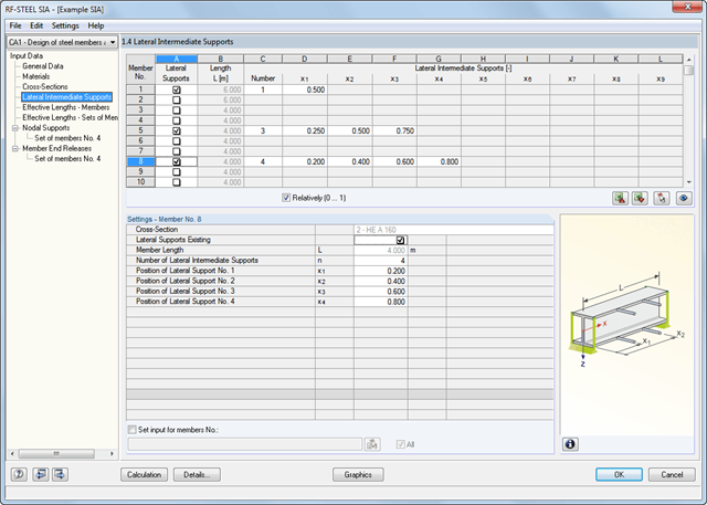
The RF-/STEEL SIA add-on module requires members and sets of members, as well as load cases, load combinations, and result combinations to be designed. In the next steps, you can adjust the preset definitions of lateral intermediate supports and effective lengths.
In the case of continuous members, it is possible to define individual support conditions and eccentricities of each intermediate node of single members. A special FEA tool then determines the critical loads and moments required for the stability analysis in these situations.
The program creates a reinforcement proposal for the top and the bottom plate reinforcement. The program searches automatically for the most favorable reinforcement combination, with a mat and added rebars. If required, the rebars are distributed across two reinforcement areas by curtailment. It is possible to modify the reinforcement proposal individually by:
- Application of another mat type
- Individual control of diameter and spacing of added rebars
- Free selection of reinforcement area widths
- Individual curtailment of reinforcements
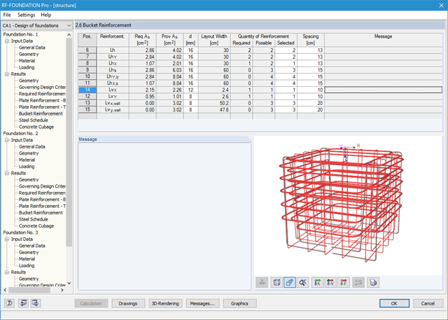
You can display the foundation in excellent rendering quality, including reinforcement. In the rendering, as well as in up to seven different dimensioned reinforcement drawings ready for construction, the module provides a solution proposal for bucket design. It is possible to modify the number, position, diameter, and spacing of used rebars here as well. You can also determine the shape of the applied links.
The dimensions of the foundation plate and bucket can be determined by the add-on module, or can be user-defined. Clearly arranged windows display the results of each performed design, including all intermediate values. They are covered in a reduced printout report providing a verifiable structural analysis.
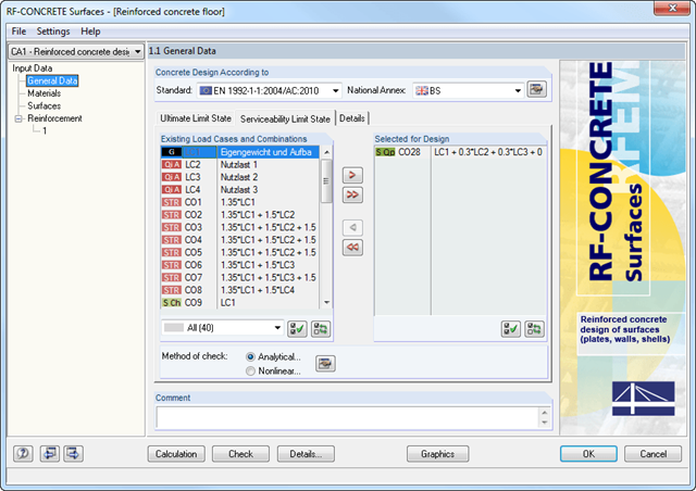
The deformation analysis with RF-CONCRETE Deflect can be activated in the settings for the analytical serviceability limit state design in the RF-CONCRETE Surfaces module. Consideration of long-term effects (creep and shrinkage) and tension stiffening between cracks can also be managed in the dialog box above. The creep coefficient and shrinkage strain are calculated using the specified input parameters or defined individually.
You can specify the deformation limit value individually for each surface or for an entire surface group. The max. deformation is defined as the allowable limit value. In addition, you have to specify whether the undeformed or the deformed system is to be used for the design check.
After the calculation, the module shows clearly arranged tables listing the required reinforcement and the results of the serviceability limit state design. All intermediate values are included in a comprehensible manner.
The results of RF‑CONCRETE Members are displayed as result diagrams of each member. The reinforcement proposals of the longitudinal and the shear reinforcement, including sketches, are documented in accordance with current practice. It is possible to edit the reinforcement proposal and to adjust, for example, the number of members and the anchorage. The modifications will be updated automatically. A concrete cross‑section, including reinforcement, can be visualized in a 3D rendering. This way, the program provides an optimal documentation option to create reinforcement drawings, including steel schedule.
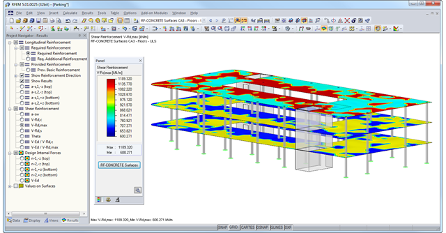
The results of RF-CONCRETE Surfaces can be displayed graphically as isolines, isosurfaces, or numeric values. It is possible to sort the longitudinal reinforcement display by required reinforcement, required additional reinforcement, provided basic or additional reinforcement, and provided total reinforcement. The isolines of the longitudinal reinforcement can be exported as a DXF file for further use in CAD programs as a basis for reinforcement drawings.
In order to facilitate the data input, surfaces, members, sets of members, materials, surface thicknesses, and cross-sections are preset in RFEM. It is possible to select the elements graphically using the [Select] function. The program provides access to the global material and section libraries. Load cases, load combinations, and result combinations can be combined in various design cases. You can enter all geometric and standard-specific reinforcement settings for the reinforced concrete design in a segmented window. The geometry entries in both RF‑CONCRETE modules differ from each other.
- In the RF-CONCRETE Members add-on module, for example, This includes, for example, specifications for the curtailment of rebars, number of layers, cutting ability of links, and anchorage type. For the fire resistance design of reinforced concrete members, you have to define the fire resistance class, the fire‑related material properties, and the cross‑section sides exposed to fire.
- In the RF‑CONCRETE Surfaces add‑on module, it is necessary to specify, for example, the concrete cover, the reinforcement direction, the minimum and the maximum reinforcement, the basic reinforcement to be applied, or the designed longitudinal reinforcement, as well as the rebar diameter.
Surfaces or members can be summarized in special "reinforcement groups", each defined by different design parameters. This way, it is possible to efficiently calculate alternative designs with different boundary conditions or modified cross‑sections.
The maximum and minimum extreme values (the envelope) are displayed in result tables and graphics. It is possible to add them to the global RSTAB printout report.
You can also design the internal forces of super combinations in many RSTAB add-on modules.