
In the Modal Analysis add-on, you have the option to automatically increase the sought eigenvalues until reaching a defined effective modal mass factor. All translational directions activated as masses for the modal analysis are taken into account.
Thus, it is possible to easily calculate the required 90% of the effective modal mass for the response spectrum method.

The time history analysis is performed with the modal analysis or the linear implicit Newmark analysis. The time history analysis in this add-on is limited to linear structural systems. Although the modal analysis represents a fast algorithm, it is necessary to use a certain number of eigenvalues to ensure the required accuracy of results.
The implicit Newmark analysis is a very precise method, independent of the number of eigenvalues used, but requires sufficient small time steps for the calculation.

Did you use the eigenvalue solver of the add-on to determine the critical load factor within the stability analysis? In this case, you can then display the governing mode shape of the object to be designed as a result.

Is the calculation finished? The results of the modal analysis are then available both graphically and in tables. Display the result tables for the load case or the load cases of the modal analysis. Thus, you can see the eigenvalues, angular frequencies, natural frequencies, and natural periods of the structure at first glance. The effective modal masses, modal mass factors, and participation factors are also clearly displayed.

- Stability analyses for flexural buckling, torsional buckling, and flexural-torsional buckling under compression
- Import of the effective lengths from the calculation using the Structure Stability add-on
- Graphical input and check of the defined nodal supports and effective lengths for stability analysis
- Determination of the equivalent member lengths for tapered members
- Consideration of Lateral-Torsional Bracing Position
- Lateral-torsional buckling analysis of the structural components subjected to moment loading
- Depending on the standard, a choice between user-defined input of Mcr, analytical method from the standard, and use of internal eigenvalue solver
- Consideration of a shear panel and a rotational restraint when using the eigenvalue solver
- Graphical display of a mode shape if the eigenvalue solver was used
- Stability analysis of structural components with the combined compression and bending stress, depending on the design standard
- Comprehensible calculation of all necessary coefficients, such as the factors for considering moment distribution or interaction factors
- Alternative consideration of all effects for the stability analysis when determining internal forces in RFEM/RSTAB (second-order analysis, imperfections, stiffness reduction, possibly in combination with the Torsional Warping (7 DOF) add-on)

Did you use the eigenvalue solver of the add-on to determine the critical load factor within the stability analysis? If so, you can then display the governing mode shape of the object to be designed as a result. The eigenvalue solver is available here for the lateral-torsional buckling analysis, depending on the design standard used.

Did you use the eigenvalue solver of the add-on to determine the critical load factor for the stability analysis? Verz well, you can then display the governing mode shape of the object to be designed as a result. The eigenvalue solver is available for the lateral-torsional buckling analysis, depending on the design standard used. You can also use the internal eigenvalue solver for the general method according to EN 1993‑1‑1, 6.3.4.
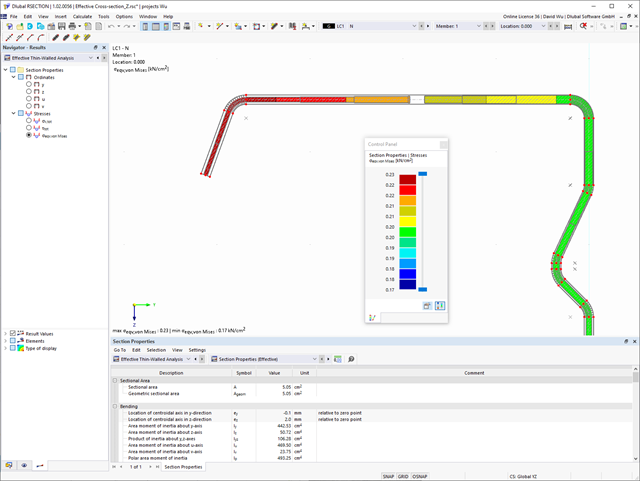
Effective Sections is an extension of the section properties program RSECTION. Compared to the RF‑/STEEL Cold-Formed Sections add-on module for RFEM 5 / RSTAB 8, the following new features have been added to Effective Sections:
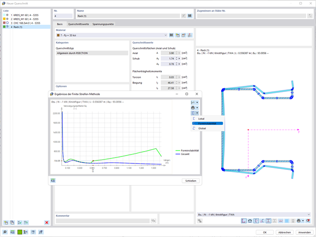
- Consideration of the effects of distortional buckling of sections via eigenvalue method
- Definition of stiffeners and buckling panels no longer necessary
- Graphical display of unit stresses
- Optional manual definition of stress points

Compared to the RF‑/TIMBER Pro add-on module (RFEM 5 / RSTAB 8), the following new features have been added to the Timber Design add-on for RFEM 6 / RSTAB 9:
- In addition to Eurocode 5, other international standards are integrated (SIA 265, ANSI/AWC NDS, CSA O86, GB 50005)
- Design of compression perpendicular to grain (support pressure)
- Implementation of eigenvalue solver for determining the critical moment for lateral-torsional buckling (EC 5 only)
- Definition of different effective lengths for design at normal temperature and fire resistance design
- Evaluation of stresses via unit stresses (FEA)
- Optimized stability analyses for tapered members
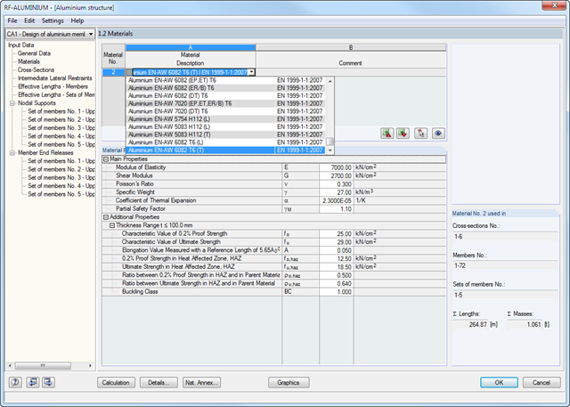
- Unification of the materials for all national annexes (only one "EN" standard is now available in the material library for a better overview)
- Display of cross-section weakenings directly in the rendering
- Output of the used design check formulas (including a reference to the used equation from the standard)
- Available for general thin-walled RSECTION cross-sections
- Classification according to
- EN 1993-1-1
- EN 1993-1-4
- EN 1999-1-1
- Determination of the effective section according to
- EN 1993-1-5
- EN 1993-1-3
- EN 1999-1-1
- Consideration of the effects of distortional buckling of cold-formed sections via eigenvalue method
- Determination of the stresses on the effective section and gross section
- Cross-section, stability, and serviceability limit state design checks of RSECTION cross-sections of Class 4 according to EN 1993‑1‑1 or EN 1999‑1‑1 in the Steel Design or Aluminum Design add-ons
- Cross-section checks for cold-formed RSECTION cross-sections according to EN 1993‑1‑3 in the Steel Design add-on
- Available for all National Annexes integrated in the Steel Design add-on

The Dlubal structural analysis software does a lot of work for you. The input parameters, which are relevant for the selected standards, are suggested by the program in accordance with the rules. Furthermore, you can enter response spectra manually.
Load cases of the type Response Spectrum Analysis define the direction in which response spectra act and which eigenvalues of the structure are relevant for the analysis. In the spectral analysis settings, you can define details for the combination rules, damping (if applicable), and zero-period acceleration (ZPA).

Did you know that Equivalent static loads are generated separately for each relevant eigenvalue and excitation direction. These loads are saved in a load case of the Response Spectrum Analysis type and RFEM/RSTAB performs a linear static analysis.

- Automatic consideration of masses from self-weight
- Direct import of masses from load cases or load combinations
- Optional definition of additional masses (nodal, linear, or surface masses, as well as inertia masses) directly in the load cases
- Optional neglect of masses (for example, mass of foundations)
- Combination of masses in different load cases and load combinations
- Preset combination coefficients for various standards (EC 8, SIA 261, ASCE 7,...)
- Optional import of initial states (for example, to consider prestress and imperfection)
- Structure Modification
- Consideration of failed supports or members/surfaces/solids
- Definition of several modal analyses (for example, to analyze different masses or stiffness modifications)
- Selection of mass matrix type (diagonal matrix, consistent matrix, unit matrix), including user-defined specification of translational and rotational degrees of freedom
- Methods for determining the number of mode shapes (user-defined, automatic - to reach effective modal mass factors, automatic - to reach the maximum natural frequency - only available in RSTAB)
- Determination of mode shapes and masses in nodes or FE mesh points
- Results of eigenvalue, angular frequency, natural frequency, and period
- Output of modal masses, effective modal masses, modal mass factors, and participation factors
- Masses in mesh points displayed in tables and graphics
- Visualization and animation of mode shapes
- Various scaling options for mode shapes
- Documentation of numerical and graphical results in printout report

In the modal analysis settings, you have to enter all data that are necessary for the determination of the natural frequencies. These are, for example, mass shapes and eigenvalue solvers.
The Modal Analysis add-on determines the lowest eigenvalues of the structure. Either you adjust the number of eigenvalues or let them determined automatically. Thus, you should reach either effective modal mass factors or maximum natural frequencies. Masses are imported directly from load cases and load combinations. In this case, you have the option to consider the total mass, load components in the global Z-direction, or only the load component in the direction of gravity.
You can manually define additional masses at nodes, lines, members, or surfaces. Furthermore, you can influence the stiffness matrix by importing axial forces or stiffness modifications of a load case or load combination.

In RFEM, you can use these three powerful eigenvalue solvers:
- Root of Characteristic Polynomial
- Method by Lanczos
- Subspace Iteration
RSTAB, on the other hand, provides you with these two eigenvalue solvers:
- Subspace Iteration
- Shifted inverse power method
The selection of the eigenvalue solver depends primarily on your model size.

As soon as the program has completed the calculation, the eigenvalues, natural frequencies and periods are listed. These result windows are integrated in the main program RFEM/RSTAB. You can find all mode shapes of the structure in tables and also have an option to display them graphically and to animate them.
All result tables and graphics are part of the RFEM/RSTAB printout report. In this way, you can ensure clearly arranged documentation. You can also export the tables to MS Excel.
- Stability analyses for flexural buckling, torsional buckling, and flexural-torsional buckling under compression
- Import of the effective lengths from the calculation using the Structure Stability add-on
- Graphical input and check of the defined nodal supports and effective lengths for stability analysis
- Lateral-torsional buckling analysis of the structural components subjected to moment loading
- Depending on the standard, a choice between user-defined input of Mcr, analytical method from the standard, and use of internal eigenvalue solver
- Consideration of a shear panel and a rotational restraint when using the eigenvalue solver
- Graphical display of a mode shape if the eigenvalue solver was used
- Stability analysis of structural components with the combined compression and bending stress, depending on the design standard
- Comprehensible calculation of all necessary coefficients, such as the factors for considering moment distribution or interaction factors
- Alternative consideration of all effects for the stability analysis when determining internal forces in RFEM/RSTAB (second-order analysis, imperfections, stiffness reduction, possibly in combination with the Torsional Warping (7 DOF) add-on)

- Stability analyses for flexural buckling, torsional buckling, and flexural-torsional buckling under compression
- Lateral-torsional buckling analysis of the structural components subjected to moment loading
- Import of the effective lengths from the calculation using the Structure Stability add-on
- Graphical input and check of the defined nodal supports and effective lengths for stability analysis
- Depending on the standard, a choice between user-defined input of Mcr, analytical method from the standard, and use of internal eigenvalue solver
- Consideration of a shear panel and a rotational restraint when using the eigenvalue solver
- Graphical display of a mode shape if the eigenvalue solver was used
- Stability analysis of structural components with the combined compression and bending stress, depending on the design standard
- Comprehensible calculation of all necessary coefficients, such as interaction factors
- Alternative consideration of all effects for the stability analysis when determining internal forces in RFEM/RSTAB (second-order analysis, imperfections, stiffness reduction, possibly in combination with the Torsional Warping (7 DOF) add-on)
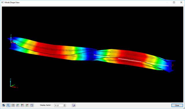
The determination of the critical buckling moment is carried out in RF-/STEEL AISC by using the eigenvalue solver which allows an exact determination of the critical buckling load.
The eigenvalue solver shows a display window of the eigenvalue graphics, which enables checking of the boundary conditions.

- Import of materials, cross-sections, and internal forces from RFEM/RSTAB
- Steel design of thin‑walled cross‑sections according to EN 1993‑1‑1:2005 and EN 1993‑1‑5:2006
- Automatic classification of cross-sections according to EN 1993-1-1:2005 + AC:2009, Cl. 5.5.2, and EN 1993-1-5:2006, Cl. 4.4 (cross-section class 4), with optional determination of effective widths according to Annex E for stresses under fy
- Integration of parameters for the following National Annexes:
-
 DIN EN 1993-1-1/NA:2015-08 (Germany)
 -
 ÖNORM B 1993-1-1:2007-02 (Austria)
 -
 NBN EN 1993-1-1/ANB:2010-12 (Belgium)
 -
 BDS EN 1993-1-1/NA:2008 (Bulgaria)
 -
 DS/EN 1993-1-1 DK NA:2015 (Denmark)
 -
 SFS EN 1993-1-1/NA:2005 (Finland)
 -
 NF EN 1993-1-1/NA:2007-05 (France)
 -
 ELOT EN 1993-1-1 (Greece)
 -
 UNI EN 1993-1-1/NA:2008 (Italy)
 -
 LST EN 1993-1-1/NA:2009-04 (Lithuania)
 -
 UNI EN 1993-1-1/NA:2011-02 (Italy)
 -
 MS EN 1993-1-1/NA:2010 (Malaysia)
 -
 NEN EN 1993-1-1/NA:2011-12 (Netherlands)
 - NS EN 1993-1-1/NA:2008-02 (Norway)
-
 PN EN 1993-1-1/NA:2006-06 (Poland)
 -
 NP EN 1993-1-1/NA:2010-03 (Portugal)
 -
 SR EN 1993-1-1/NB:2008-04 (Romania)
 -
 SS EN 1993-1-1/NA:2011-04 (Sweden)
 -
 SS EN 1993-1-1/NA:2010 (Singapore)
 -
 STN EN 1993-1-1/NA:2007-12 (Slovakia)
 -
 SIST EN 1993-1-1/A101:2006-03 (Slovenia)
 -
 UNE EN 1993-1-1/NA:2013-02 (Spain)
 -
 CSN EN 1993-1-1/NA:2007-05 (Czech Republic)
 -
 BS EN 1993-1-1/NA:2008-12 (the United Kingdom)
 -
 CYS EN 1993-1-1/NA:2009-03 (Cyprus)
 - In addition to the National Annexes (NA) listed above, you can also define a specific NA, applying user‑defined limit values and parameters.
- Automatic calculation of all required factors for the design value of flexural buckling resistance Nb,Rd
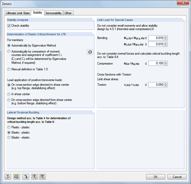
- Automatic determination of the ideal elastic critical moment Mcr for each member or set of members on every x-location according to the Eigenvalue Method or by comparing moment diagrams. You only have to define the lateral intermediate supports.
- Design of tapered members, unsymmetric sections or sets of members according to the General Method as described in EN 1993-1-1, Cl. 6.3.4
- In the case of the General Method according to Cl. 6.3.4, optional application of "European lateral-torsional buckling curve" according to Naumes, Strohmann, Ungermann, Sedlacek (Stahlbau 77 [2008], pp. 748‑761)
- Rotational restraints can be taken into account (trapezoidal sheeting and purlins)
- Optional consideration of shear panels (for example, trapezoidal sheeting and bracing)
- RF-/STEEL Warping Torsion module extension (license required) for stability analysis according to the second-order analysis as stress analysis including consideration of the 7th degree of freedom (warping)
- Module extension RF-/STEEL Plasticity (license required) for plastic analysis of cross‑sections according to Partial Internal Forces Method (PIFM) and Simplex Method for general cross‑sections (in connection with the RF‑/STEEL Warping Torsion module extension, it is possible to perform the plastic design according to the second‑order analysis)
- Module extension RF-/STEEL Cold-Formed Sections (license required) for ultimate and serviceability limit state designs for cold-formed steel members according to the EN 1993-1-3 and EN 1993-1-5 standards
- ULS design: Selection of fundamental or accidental design situations for each load case, load combination, or result combination
- SLS design: Selection of characteristic, frequent, or quasi-permanent design situations for each load case, load combination, or result combination
- Tension analysis with definable net cross-section areas for member start and end
- Weld designs of welded cross-sections
- Optional calculation of warp spring for nodal support on sets of members
- Graphic of design ratios on cross-section and in RFEM/RSTAB model
- Determination of governing internal forces
- Filter options for graphical results in RFEM/RSTAB
- Representation of design ratios and cross‑section classes in the rendered view
- Color scales in result windows
- Automatic cross-section optimization
- Transfer of optimized cross-sections to RFEM/RSTAB
- Parts lists and quantity surveying
- Direct data export to MS Excel
- Verifiable printout report
- Possibility to include the temperature curve in the report
- Design of members and sets of members for tension, compression, bending, shear, combined internal forces, and torsion
- Stability analysis of buckling and lateral-torsional buckling
- Automatic determination of critical buckling loads and critical buckling moments for general load applications and support conditions by means of a special FEA program (eigenvalue analysis) integrated in the module
- Alternative analytical calculation of the critical buckling moment for standard situations
- Optional application of discrete lateral supports to beams and continuous members
- Automatic cross-section classification (compact, noncompact, and slender)
- Serviceability limit state design (deflection)
- Cross-section optimization
- A wide range of available cross-sections, such as rolled I-sections; channel sections; T-sections; angles; rectangular and circular hollow sections; round bars; symmetrical and asymmetrical, parametric I-, T-, and angle sections; double angles
- Clearly arranged input and result windows
- Detailed result documentation including references to design equations of the used standard
- Various filter and sorting options of results, including result lists by member, cross-sections, and x-location, or by load case, load combination, and result combination
- Result table of member slenderness and governing internal forces
- Parts list with weight and solid specifications
- Seamless integration in RFEM/RSTAB
- Metric and imperial units
- Design of members and sets of members for tension, compression, bending, shear, torsion, and combined internal forces
- Stability analysis of buckling and lateral-torsional buckling
- Automatic determination of effective radius of gyration by special integrated FEA software (eigenvalue analysis) for general loading and support conditions
- Alternative analytical calculation of effective radius of gyration for standard situations
- Optional application of discrete lateral supports to beams
- Definition of nodal supports for sets of members
- Serviceability limit state design (deflection)
- Cross-section optimization
- A wide range of available cross-sections, such as rolled I-sections, channel sections, T-sections, angles, rectangular and circular hollow sections, round bars, and many others.
- Detailed result documentation including references to design equations of the used standard
- Various filter and sorting options of results, including result lists by member, cross-sections, and x-location, or by load case, load and result combination
- Result table of member slenderness and governing internal forces
- Metric and imperial units
- Design of tension, compression, bending, shear, and combined internal forces
- Stability analysis for flexural buckling and lateral-torsional buckling
- Automatic determination of critical buckling loads and critical buckling moments for general load applications and support conditions by means of a special FEA program (eigenvalue analysis) integrated in the module
- Optional application of discrete lateral supports to beams
- Automatic cross-section classification
- Deformation analysis (serviceability)
- Cross-section optimization
- Wide range of cross-sections available, such as rolled I-sections, C-sections, rectangular hollow sections, angles, double angles (arrangement flange on flange), T-sections. Welded sections: I-shaped (symmetrical and asymmetrical about major axis), channel sections (symmetrical about major axis), rectangular hollow sections (symmetrical and asymmetrical about major axis), angles, round pipes, and round bars
- Clearly arranged result tables
- Detailed result documentation including references to design equations of the used standard
- Various filter and sorting options of results, including result lists by member, cross-sections, x-location, or by load case, load and result combination
- Result table of member slenderness and governing internal forces
- Parts list with weight and solid specifications
- Seamless integration in RFEM/RSTAB
- Metric and imperial units
- Design of tension, compression, bending, shear, and combined internal forces
- Stability analysis for flexural buckling and lateral-torsional buckling
- Automatic determination of critical buckling loads and critical buckling moments for general load applications and support conditions by means of a special FEA program (eigenvalue analysis) integrated in the module
- Optional application of discrete lateral supports to beams
- Automatic cross-section classification (Class 1 to 3)
- Deformation analysis (serviceability)
- Cross-section optimization
- Wide range of cross-sections available, such as rolled I-sections, C-sections, rectangular hollow sections, angles, double angles (arrangement flange on flange), T-sections. Welded sections: I-shaped (symmetrical and asymmetrical about major axis), channel sections (symmetrical about major axis), rectangular hollow sections (symmetrical and asymmetrical about major axis), angles, round pipes, and round bars
- Clearly arranged result tables
- Detailed result documentation including references to design equations of the used standard
- Various filter and sorting options of results, including result lists by member, cross-sections, x-location, or by load case, load and result combination
- Result table of member slenderness and governing internal forces
- Parts list with weight and solid specifications
- Seamless integration in RFEM/RSTAB
- Metric and imperial units
- Design of members and sets of members for compression, bending, shear, and combined actions
- Stability analysis of buckling and lateral-torsional buckling
- Automatic determination of critical buckling loads and critical buckling moments for general load applications and support conditions by means of a special FEA program (eigenvalue analysis) integrated in the module
- Optional application of discrete lateral supports to beams
- Automatic cross-section classification (Class 1 to 4)
- Deformation analysis (serviceability)
- Cross-section optimization
- A wide range of available cross-sections, such as rolled I-sections; channel sections; T-sections; angles; rectangular and circular hollow sections; round bars; symmetrical and asymmetrical, parametric I-, T-, and angle sections; double angles
- Optional import of buckling lengths from RF-STABILITY/RSBUCK
- Detailed result documentation including references to design equations of the used standard
- Various filter and sorting options of results including result lists by member, cross-section, x-location, or by load cases, load and result combinations
- Result table of member slenderness and governing internal forces
- Parts list with weight and solid specifications
_(2)_(1).png?mw=640&hash=7e2297521472072f1532ffd2c7baee22c3025844)
- Design of members and sets of members for tension, compression, bending, shear, combined internal forces, and torsion
- Stability analysis of buckling and lateral-torsional buckling
- Automatic determination of critical buckling loads and critical buckling moments for general load applications and support conditions by means of a special FEA program (eigenvalue analysis) integrated in the module
- Alternative analytical calculation of the critical buckling moment for standard situations
- Optional application of discrete lateral supports to beams and continuous members
- Automatic cross-section classification (compact, noncompact, and slender)
- Serviceability limit state design (deflection)
- Cross-section optimization
- A wide range of available cross-sections, such as rolled I-sections, channel sections, T-sections, angles, rectangular and circular hollow sections, round bars, symmetrical, asymmetrical, parameterized I-, T-, and angle sections, as well as user-defined SHAPE‑THIN sections
- Clearly arranged input and result windows
- Detailed result documentation including references to design equations of the used standard
- Various filter and sorting options of results including result lists by member, cross-section, x-location, or by load cases, load and result combinations
- Result table of member slenderness and governing internal forces
- Parts list with weight and solid specifications
- Seamless integration in RFEM/RSTAB
- Metric and imperial units
- Automatic consideration of masses from self-weight
- Direct import of masses from load cases or load combinations
- Optional definition of additional masses (nodal, linear, surface masses, as well as inertia masses)
- Combination of masses in different mass cases and mass combinations
- Preset combination coefficients according to EC 8
- Optional import of normal force distributions (in order to consider prestress, for example)
- Stiffness modification (for example, deactivated members or stiffnesses can be imported from RF-/CONCRETE)
- Consideration of failed supports or members
- Definition of several natural vibration cases (for example, to analyze different masses or stiffness modifications)
- Results of eigenvalue, angular frequency, natural frequency, and period
- Determination of mode shapes and masses in nodes or FE mesh points
- Results of modal masses, effective modal masses, and modal mass factors
- Visualization and animation of mode shapes
- Various scaling options for mode shapes
- Documentation of numerical and graphical results in the printout report
- Design of tension, compression, bending, shear, and combined internal forces
- Stability analysis for flexural buckling, torsional buckling, and lateral-torsional buckling
- Automatic determination of critical buckling loads and critical moment for lateral-torsional buckling by means of integrated FEA program (eigenvalue analysis) from boundary conditions of loads and supports
- Optional application of discrete lateral supports to beams
- Automatic or manual cross-section classification
- Integration of parameters from National Annexes (NA) of the following countries:
-
DIN EN 1999-1-1/NA:2010-12 (Germany)
-
NBN EN 1999-1-1/ANB:2011-03 (Belgium)
-
DK EN 1999-1-1/NA:2013-05 (Denmark)
-
SFS EN 1999-1-1/NA:2016-12 (Finland)
-
ELOT EN 1999-1-1/NA:2010-11 (Greece)
-
 IS EN 1999-1-1/NA:2010-03 (Ireland)
 -
UNI EN 1999-1-1/NA:2011-02 (Italy)
-
LST EN 1999-1-1/NA:2011-09 (Lithuania)
-
UNI EN 1999-1-1/NA:2011-02 (Italy)
-
NEN EN 1999-1-1/NB:2011-12 (Netherlands)
-
PN EN 1999-1-1/NA:2011-01 (Poland)
-
SS EN 1999-1-1/NA:2011-04 (Sweden)
-
STN EN 1999-1-1/NA:2010-01 (Slovakia)
-
BS EN 1999-1-1/NA:2009 (the United Kingdom)
-
STN EN 1999-1-1/NA:2009-02 (Slovakia)
-
CYS EN 1999-1-1/NA:2009-07 (Cyprus)
-
- Serviceability limit state design for characteristic, frequent, or quasi-permanent design situation
- Consideration of transverse welds
- Variety of cross-sections provided; for example, I‑sections, C‑sections, rectangular hollow sections, square sections, angles with equal and unequal legs, flat steel, round bars
- Clearly arranged result tables
- Automatic cross-section optimization
- Detailed result documentation with references to the design equations used and described in the standard
- Filter and sorting options for results, including result lists by member, cross‑section, and x‑location, or by load cases, load combinations, and result combinations
- Result window of member slenderness and governing internal forces
- Parts list with weight and solid specifications
- Seamless integration in RFEM/RSTAB
- Metric and imperial units
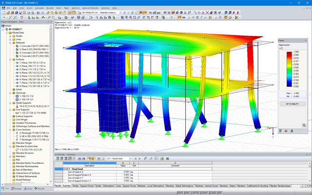
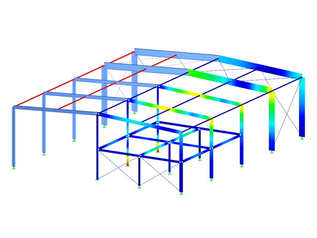
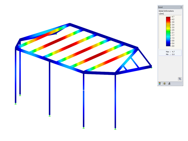
The first results presented are the critical load factors. This allows for an evaluation of stability risks. For member models, the effective lengths and critical loads of the members are output in tabular form.
In the next result windows, you can check the normalized eigenvalues sorted by node, member, and surface. The eigenvalue graphic allows for evaluation of the buckling behavior. The graphical display makes it easier to take countermeasures.