11 Wyniki
Wyświetl wyniki:
Sortuj według:
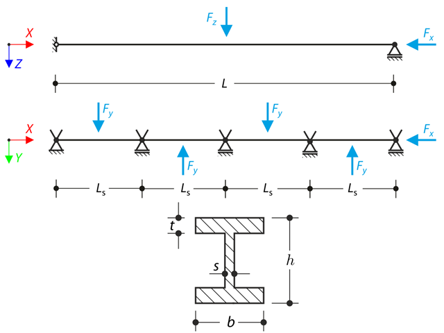
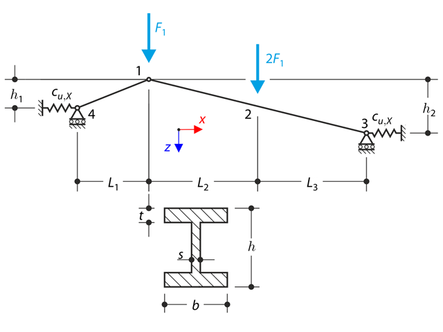
Belka ciągła z czterema przęsłami jest obciążona siłami osiowymi i zginającymi (zastępuje imperfekcje). Wszystkie podpory są widełkowe - deplanacja jest dowolna. Określ przemieszczenia uy i uz, momenty My, Mz, Mω i MTpri oraz obrót φx. Przykład obliczeniowy oparty jest na przykładzie wprowadzonym przez Gensichen i Lumpe.
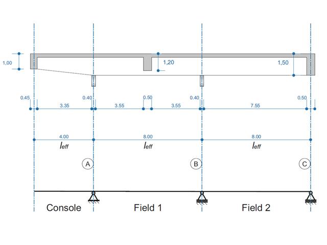
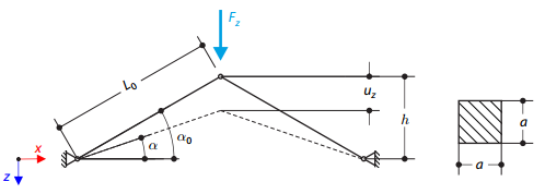
Belka żelbetowa została zaprojektowana jako belka dwuprzęsłowa na wsporniku. Przekrój zmienia się na całej długości wspornika (przekrój o zmiennym przekroju). Obliczane są siły wewnętrzne oraz wymagane zbrojenie podłużne i zbrojenie na ścinanie dla stanu granicznego nośności.
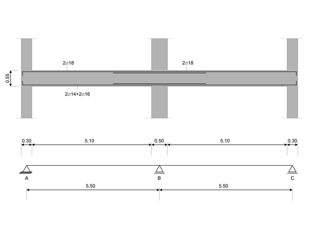
W tym przykładzie obliczeniowym obliczane są wartości nośności sił tnących na belkach zgodnie z EN 1998-1, 5.4.2.2 i 5.5.2.1 oraz nośność słupów przy zginaniu zgodnie z 5.2.3.3(2 ). System składa się z dwuprzęsłowej belki żelbetowej o rozpiętości 5,50 m. Belka jest częścią układu ramowego. Otrzymane wyniki są porównywane z wynikami w [1].
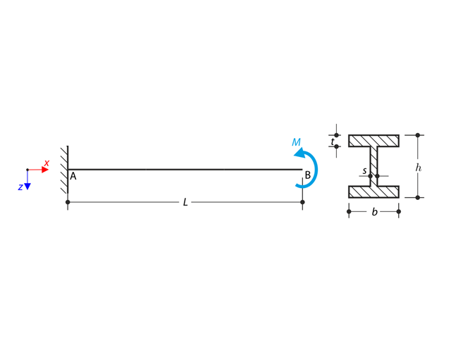
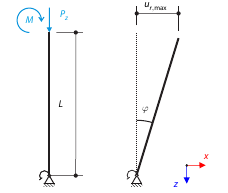
Wspornik o profilu dwuteowym jest podparty na lewym końcu i jest obciążony momentem obrotowym M. Celem tego przykładu jest porównanie podpory nieruchomej z podporą widełkową i zbadanie zachowania się niektórych reprezentatywnych wielkości. Przeprowadzane jest również porównanie z rozwiązaniem za pomocą płyt. Przykład obliczeniowy oparty jest na przykładzie wprowadzonym przez Gensichen i Lumpe.
Konstrukcja wykonana z kratownic o profilu dwuteowym jest podparta na obu końcach przez sprężyste podpory ślizgowe i obciążona siłami poprzecznymi. W tym przykładzie pominięto ciężar własny . Należy określić ugięcie konstrukcji, moment zginający, siłę normalną w danych punktach testowych oraz ugięcie poziome podpory sprężystej.
Model oparty jest na przykładzie 4 z [1]: Płyta podparta punktowo.
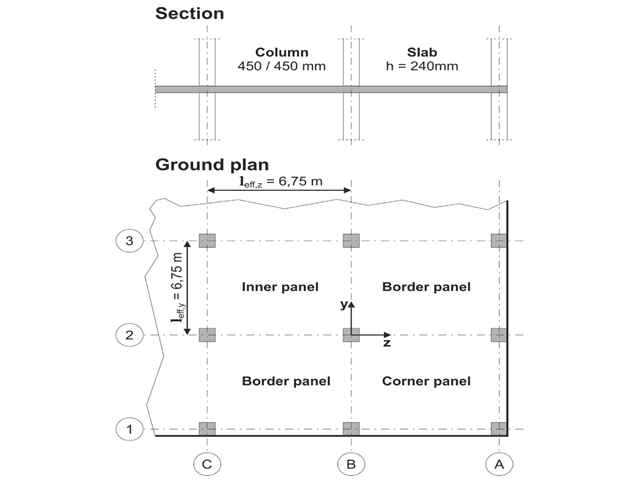
Należy zaprojektować płaską płytę budynku biurowego o wrażliwych na zarysowania ścianach lekkich. Należy zbadać panele wewnętrzne, brzegowe i narożne. Słupy i płyta są połączone monolitycznie. Słupy skrajne i narożne są zlicowane z krawędzią płyty. Osie słupów tworzą siatkę kwadratową. Jest to układ sztywny (budynek usztywniony ścianami usztywniającymi).
Budynek biurowy ma 5 kondygnacji i ma wysokość 3.000 m. Warunki środowiskowe, które należy przyjąć, określane są jako „zamknięte przestrzenie wewnętrzne”. Występują głównie oddziaływania statyczne.
Celem tego przykładu jest określenie momentów w płycie i wymaganego zbrojenia nad słupami przy pełnym obciążeniu.
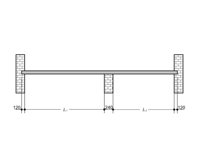
Płytę żelbetową wewnątrz budynku należy projektować jako pas o długości 1,0 m wraz z prętami. Płyta stropowa jest jednoosiowo rozpięta i przebiega przez dwa przęsła. Płyta jest mocowana do ścian murowanych za pomocą podpór swobodnie obracających się. Podpora środkowa ma szerokość 240 mm, a dwie podpory krawędziowe mają szerokość 120 mm. Oba przęsła są poddane obciążeniu użytkowemu kategorii C: obszary zborów.
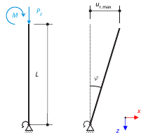
Rozważmy sztywną rurę rusztowania, zamocowaną u dołu za pomocą podpory węzłowej rusztowania i obciążoną zarówno momentem, jak i siłą. Calculate the maximum deflection with consideration of initial slippage.
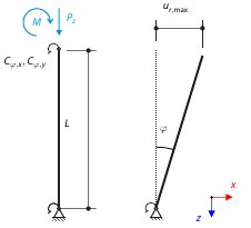
Rozważmy sztywną rurę rusztowania, zamocowaną u dołu za pomocą podpory węzłowej rusztowania i obciążoną zarówno momentem, jak i siłą. Calculate the maximum radial deflection by exceeding the capacity of the scaffolding support.
Konstrukcja składa się z dwóch kratownic wbudowanych w podpory przegubowe. The structure is loaded by concentrated force. The self-weight is neglected. Determine the relationship between the loading force and the deflection, considering large deformations.
Rozważmy sztywną rurę rusztowania, zamocowaną u dołu za pomocą podpory węzłowej rusztowania i obciążoną zarówno momentem, jak i siłą. Self-weight is not considered. Considering an infinitely rigid beam, determine the maximum radial deflection.