45 Wyniki
Wyświetl wyniki:
Sortuj według:
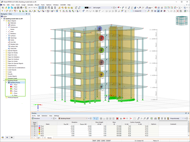
Model budynku jest jednym ze specjalnych rozszerzeń w programie RFEM 6. Jest to przydatne narzędzie do modelowania, za pomocą którego można łatwo tworzyć kondygnacje budynków i nimi manipulować. Model budynku można aktywować na początku procesu modelowania lub po jego zakończeniu.

Jedną z innowacji w programie RFEM 6 jest nowy sposób projektowania połączeń stalowych. W przeciwieństwie do programu RFEM 5, w którym wymiarowanie połączeń stalowych opiera się na rozwiązaniu analitycznym, rozszerzenie Połączenia stalowe w programie RFEM 6 oferuje rozwiązanie dla połączeń stalowych w oparciu o analizę MES.

W tym artykule technicznym omówimy podstawowe kwestie dotyczące korzystania z rozszerzenia Skręcanie skrępowane (7 stopni swobody). Jest ono w pełni zintegrowane z programem głównym i umożliwia uwzględnienie deplanacji przekroju podczas obliczania elementów prętowych. W połączeniu z rozszerzeniami Analiza stateczności oraz Wymiarowanie stali, możliwe jest przeprowadzenie obliczeń wyboczenia giętno-skrętnego z siłami wewnętrznymi zgodnie z analizą drugiego rzędu oraz uwzględnieniem imperfekcji.

Analiza sejsmiczna w programie RFEM 6 jest możliwa przy użyciu rozszerzeń analizy modalnej i analizy spektrum odpowiedzi. Ogólna koncepcja analizy sejsmicznej w programie RFEM 6 opiera się na utworzeniu przypadku obciążenia do analizy modalnej lub analizy spektrum odpowiedzi. Grupy norm dla tych analiz są ustawiane w zakładce Normy II w oknie Dane podstawowe modelu.
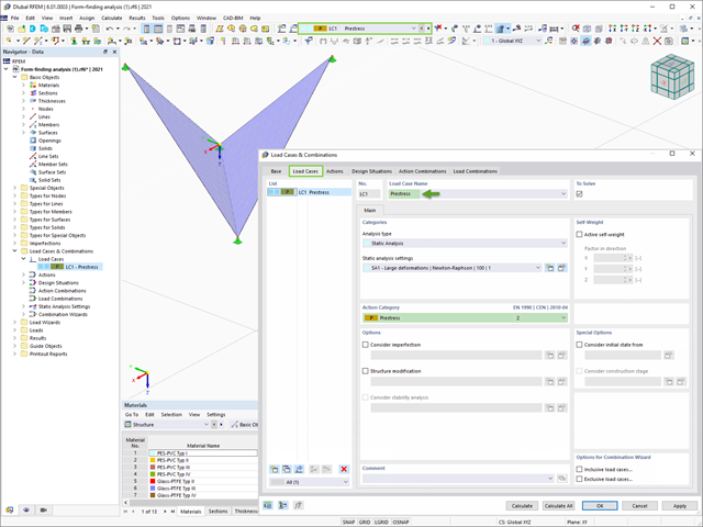
Program RFEM 6 zawiera rozszerzenie Form-Finding do określania kształtów równowagi modeli powierzchni obciążonych rozciąganiem i prętów obciążonych siłami osiowymi. Aktywuj ten dodatek w Danych bazowych modelu i użyj go, aby znaleźć położenie geometryczne, w którym naprężenie wstępne lekkich konstrukcji jest w równowadze z istniejącymi warunkami brzegowymi.

W tym artykule opisano, w jaki sposób płaska płyta budynku mieszkalnego jest modelowana w programie RFEM 6 i wymiarowana zgodnie z Eurokodem 2. Płyta ma grubość 24 cm i jest podparta na słupach o długości 45/45/300 cm w rozstawie co 6,75 m (rysunek 1). Słupy są modelowane jako sprężyste podpory węzłowe poprzez zdefiniowanie sztywności sprężystej na podstawie warunków brzegowych (rysunek 2). Jako materiały wybrano beton C35/45 i stal zbrojeniową B 500 S (A).

Obliczenia konstrukcji złożonych za pomocą oprogramowania do analizy elementów skończonych są zazwyczaj przeprowadzane na całym modelu. Jednak wznoszenie tego typu konstrukcji jest procesem wieloetapowym, w którym ostateczny stan konstrukcji uzyskuje się poprzez połączenie poszczególnych elementów konstrukcyjnych. Aby uniknąć błędów w obliczeniach ogólnych modeli, należy wziąć pod uwagę wpływ procesu konstrukcyjnego. W programie RFEM 6 jest to możliwe za pomocą rozszerzenia Analiza etapów budowy (CSA).

Nowa generacja oprogramowania RFEM umożliwia przeprowadzanie obliczeń stateczności zbieżnych prętów drewnianych zgodnie z metodą prętów zastępczych. Zgodnie z tą metodą obliczenia można przeprowadzić, jeżeli spełnione są wytyczne normy DIN 1052, sekcja E8.4.2 dla zmiennych przekrojów. W różnych publikacjach technicznych metoda ta jest również stosowana w przypadku Eurokodu 5. W tym artykule pokazano, jak zastosować metodę prętów zastępczych dla belki dachowej o zbieżnej wysokości.
Obliczenia na przebicie zgodnie z EN 1992-1-1 należy przeprowadzić dla płyt poddanych obciążeniu skupionemu lub reakcji. Węzeł, w którym przeprowadzana jest analiza nośności na przebicie (tj. w miejscu, w którym występuje problem z przebiciem) nazywany jest węzłem odporności na przebicie. Obciążenie skupione w tych węzłach może zostać wprowadzone przez słupy, siłę skupioną lub podpory węzłowe. Koniec przyłożenia obciążenia liniowego na płyty również jest traktowany jako obciążenie skupione, dlatego należy również kontrolować nośność na ścinanie na końcach, narożach i końcach ścian oraz na końcach lub narożach obciążeń liniowych i podpór liniowych.

Zgodnie z EN 1992-1-1 [1] belka jest prętem, którego rozpiętość jest nie mniejsza niż 3-krotna całkowita wysokość przekroju. W przeciwnym razie element konstrukcyjny należy traktować jako belkę-ścianę. Zachowanie belek-ścian (tj. belek o rozpiętości mniejszej niż 3-krotna wysokość przekroju) różni się od zachowania belek-ścian (tj. belek o rozpiętości trzykrotnie większej niż wysokość przekroju).
Projektowanie belek-ścian jest jednak często konieczne podczas analizy elementów konstrukcyjnych konstrukcji żelbetowych, ponieważ są one wykorzystywane do budowy nadproży okiennych i drzwiowych, podciągów i podciągów, połączeń między płytami dwupoziomowymi oraz konstrukcji ramowych.
Projektowanie belek-ścian jest jednak często konieczne podczas analizy elementów konstrukcyjnych konstrukcji żelbetowych, ponieważ są one wykorzystywane do budowy nadproży okiennych i drzwiowych, podciągów i podciągów, połączeń między płytami dwupoziomowymi oraz konstrukcji ramowych.