68 Wyniki
Wyświetl wyniki:
Sortuj według:

Każdego dnia tysiące inżynierów konstrukcyjnych projektują elementy konstrukcyjne, korzystając z wzorów kontroli projektu, uwzględniających krytyczne obciążenie wyboczeniowe. Ale skąd wzięły się te starożytne wzory, które opracował ponad 200 lat temu i które stanowią podstawę wszystkich trzech koncepcji projektowania konstrukcji stalowych?

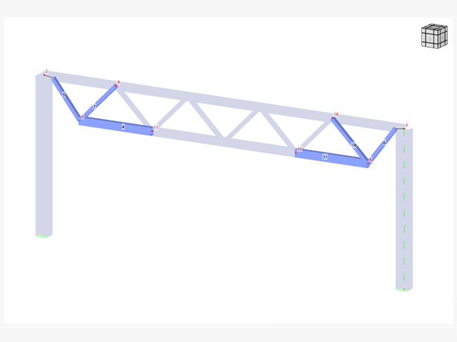
W tym artykule przedstawiono model połączenia zakładkowego płatwi ZL na dachu jednospadowym, obliczony w rozszerzeniu Połączenia stalowe i porównany z tabelą nośności podaną przez producenta.
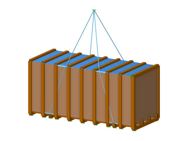
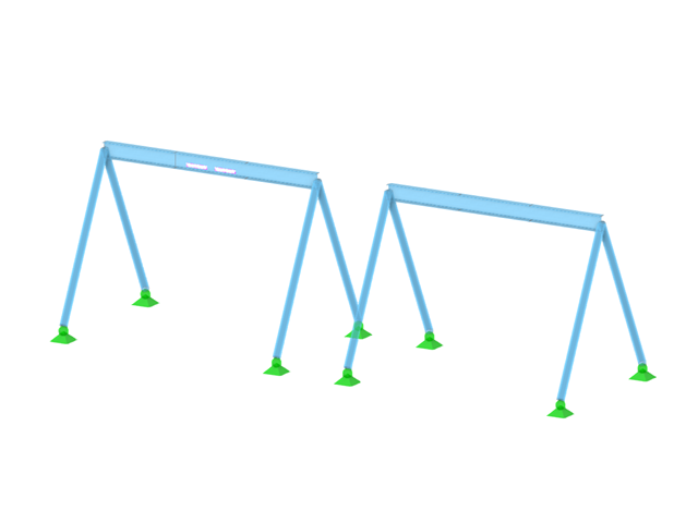
W tym artykule skrzynia na towary ciężkie jest obliczana zgodnie z wytycznymi Bundesverband Holzpackmittel (HPE). Obliczane są przypadki obciążeń dla obsługi dźwigiem i transportu morskiego.
W wielu konstrukcjach szkieletowych zastosowanie prostego pręta nie jest już wystarczające. Często należy wziąć pod uwagę osłabienia przekroju lub otwory w belkach betonowych. Dla takich zastosowań dostępny jest typ pręta "Model powierzchniowy". Można go można zintegrować z modelem jak w przypadku każdego innego pręta i oferuje on wszystkie opcje modelu powierzchniowego. Ten artykuł techniczny pokazuje zastosowanie pręta typu Model powierzchniowy w istniejącym układzie konstrukcyjnym i opisuje integrację otworów pręta.
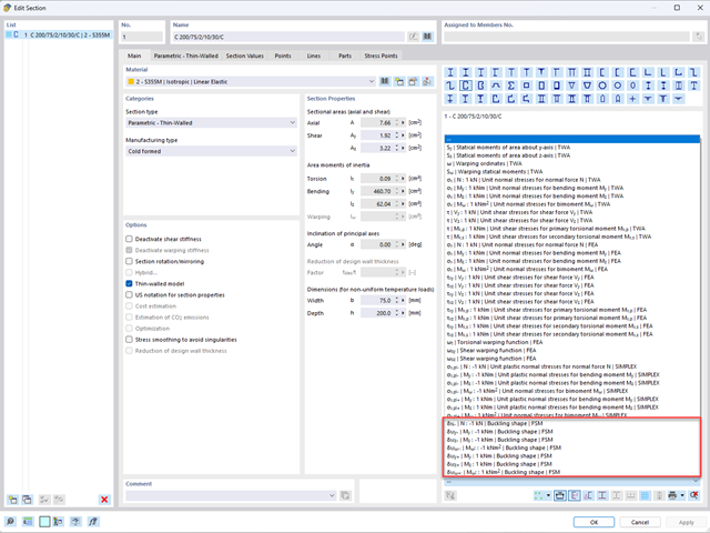
Aby umożliwić ocenę wpływu lokalnych zjawisk stateczności smukłych elementów, w programach RFEM 6 i RSTAB 9 można przeprowadzić liniową analizę obciążenia krytycznego na poziomie przekroju. Poniższy artykuł poświęcony jest podstawom obliczeń i interpretacji wyników.
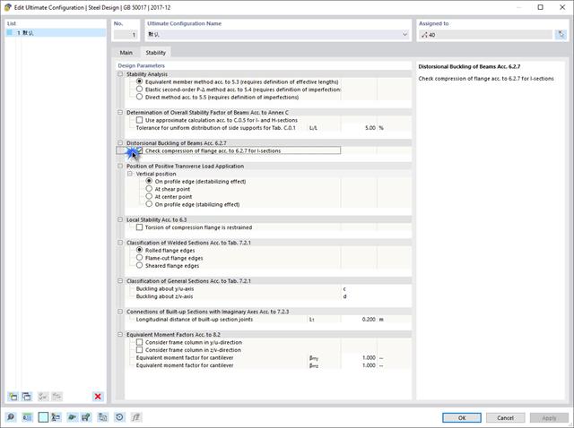
Jeżeli na górnej półce znajduje się płyta betonowa, działa ona jak podpora boczna (konstrukcja zespolona) i zapobiega problemom ze statecznością przy wyboczeniu skrętnym. Jeżeli moment zginający jest ujemny, dolna półka jest obciążona, a górna rozciągana. Jeżeli podparcie boczne nie jest wystarczające ze względu na sztywność środnika, kąt pomiędzy dolną półką a linią nacięcia środnika jest zmienny, przez co istnieje możliwość wystąpienia niestateczności wymiarowej dolnej półki.
Połączenia stalowe w programie RFEM 6 można tworzyć poprzez wprowadzenie wstępnie zdefiniowanych komponentów w rozszerzeniu Połączenia stalowe. Lista tych elementów jest stale rozszerzana, aby ułatwić modelowanie połączeń stalowych. W tym artykule przedstawiamy blachę łączącą, która została niedawno dodana do biblioteki rozszerzenia.
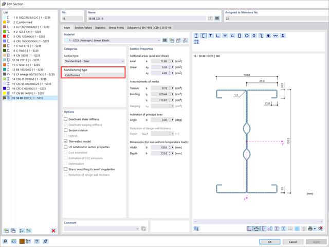
W tym artykule przedstawiono wymiarowanie przekrojów stalowych formowanych na zimno zgodnie z EN 1993-1-3, sekcja 6.1.6 w programie RFEM 6. Ponieważ temat jest nadal rozwijany, przedstawione zostaną aktualnie dostępne opcje.

Wymiarowanie prętów stalowych formowanych na zimno zgodnie z AISI S100-16 jest teraz dostępne w programie RFEM 6. Design can be accessed by selecting “AISC 360” as the standard in the Steel Design add-on. “AISI S100” is then automatically selected for the cold-formed design (Image 01).

Niniejszy artykuł jest związany z trwającym projektem, w ramach którego opracowywany i wdrażany jest cyfrowy bliźniak konstrukcyjny mostu Kalix w Szwecji.
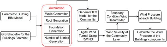
W artykule tym opracowano nowatorskie podejście do generowania modeli CFD na poziomie miejscowości poprzez połączenie modelowania informacji o budynku (BIM) i systemów informacji geograficznej (GIS) w celu zautomatyzowania generowania trójwymiarowego modelu terenu o wysokiej rozdzielczości, który zostanie wykorzystany jako dane wejściowe dla cyfrowego tunelu aerodynamicznego z wykorzystaniem RWIND.
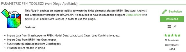
W tym artykule opisano rozwój Parametric FEM Toolbox i niektóre z możliwych przepływów pracy przy użyciu tego nowego narzędzia.
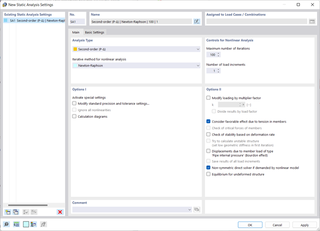
Uwzględnianie efektów drugiego rzędu p-δ w programach RFEM 6 i RSTAB 9
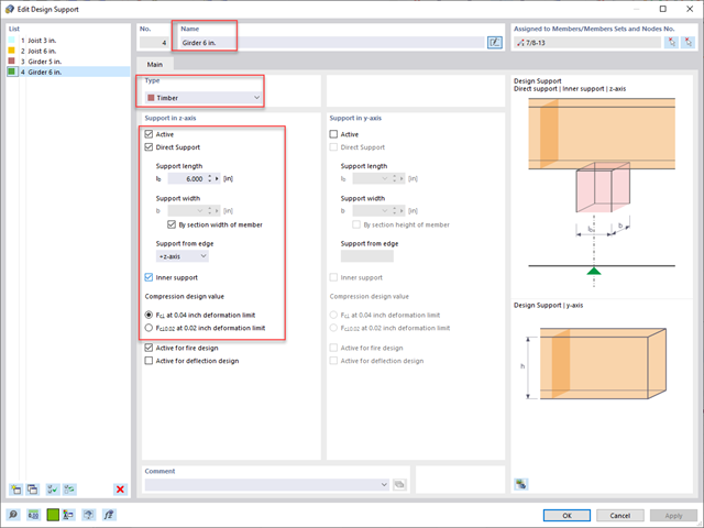
Standardowym rozwiązaniem w konstrukcji prętów drewnianych jest możliwość łączenia mniejszych prętów poprzez podparcie na większym dźwigarze. Dodatkowo warunki na końcach pręta mogą uwzględniać podobną sytuację, w której belka jest oparta na podporze. W obu przypadkach belka musi być zaprojektowana tak, aby uwzględniała nośność w poprzek włókien zgodnie z NDS 2018 s. 3.10.2 i CSA O86:19 punkty 6.5.6 i 7.5.9. W ogólnych programach do projektowania statyczno-wytrzymałościowego zazwyczaj nie jest możliwe przeprowadzenie pełnej kontroli obliczeń, ponieważ powierzchnia docisku jest nieznana. Jednak w programie RFEM 6 nowej generacji i rozszerzeniu Projektowanie konstrukcji drewnianych dodana funkcja "podpór obliczeniowych" umożliwia teraz użytkownikom uwzględnienie docisku NDS i CSA prostopadle do warunków obliczeniowych.

Jedną z innowacji w programie RFEM 6 jest nowy sposób projektowania połączeń stalowych. W przeciwieństwie do programu RFEM 5, w którym wymiarowanie połączeń stalowych opiera się na rozwiązaniu analitycznym, rozszerzenie Połączenia stalowe w programie RFEM 6 oferuje rozwiązanie dla połączeń stalowych w oparciu o analizę MES.
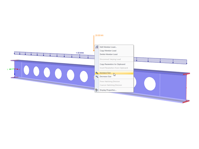
Die Darstellungsgröße der Lastvektoren kann schnell im Last-Kontextmenü angepasst werden: Klicken Sie mit der rechten Maustaste auf das Lastsymbol und wählen dann im Menü die Option "Anzeigegröße vergrößern" oder "Anzeigegröße verkleinern".
Konstrukcje różnie reagują na działanie wiatru, w zależności od sztywności, masy i tłumienia. Zasadniczo rozróżnia się budynki, które są podatne na drgania oraz takie, które nie są na nie podatne.
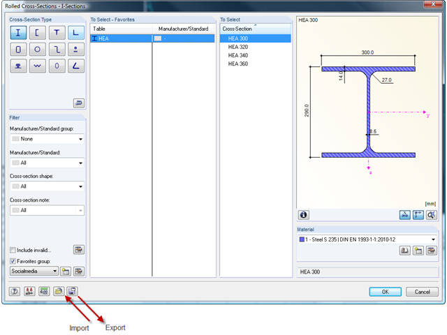
Die Querschnittsbibliothek in RFEM 5 und RSTAB 8 bietet die Option, bestimmte Querschnittselektionen in verschiedenen Favoriten-Gruppen abzuspeichern.
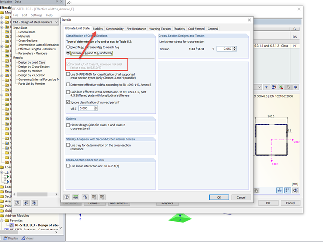
Die Klassifizierung der Querschnitte nach EN 1993-1-1 anhand der Tabelle 5.2 stellt eine einfache Methode zum Nachweis des lokalen Beulens von Querschnittsteilen dar. Für Querschnitte der Querschnittsklasse 4 ist anschließend die Ermittlung von effektivem Querschnittswerten nach EN 1993-1-5 notwendig, um den Einfluss des lokalen Beulens mit bei den Tragfähigkeitsnachweisen zu berücksichtigen.
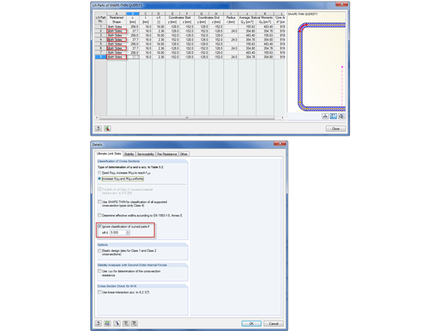
Die Klassifizierung von Querschnitten nach EN 1993-1-1 und EN 1993-1-5 kann im Zusatzmodul RF-/STAHL EC3 automatisch durchgeführt werden. Die maximalen c/t Verhältnisse sind in der Norm für gerade Querschnittsteile vorgegeben. Für gekrümmte Querschnittsteile gibt es keine normativen Vorgaben und daher kann die Querschnittsklassifizierung für diese Querschnittsteile nicht durchgeführt werden.