56 Wyniki
Wyświetl wyniki:
Sortuj według:

W rozszerzeniu Analiza etapów budowy (CSA) można używać przekrojów złożonych, dzięki zastosowaniu przekrojów etapowanych. Ten typ przekroju umożliwia aktywację lub dezaktywację poszczególnych części przekroju typu "Parametryczny - Masywny II" na poszczególnych etapach budowy.

Wynik obliczeń sejsmicznych jest podzielony na dwie sekcje: wymagania dotyczące prętów i połączeń.
"Wymagania sejsmiczne" zawierają Wymaganą wytrzymałość na zginanie i Wymaganą wytrzymałość na ścinanie połączenia belka-słup dla ram sprężystych. Są one wyszczególnione w zakładce 'Połączenia ram momentowych według prętów'. W przypadku ram stężonych w zakładce 'Połączenie stężone według pręta' podawana jest Wymagana wytrzymałość połączenia na rozciąganie oraz Wymagana wytrzymałość połączenia na ściskanie stężeń.
Przeprowadzone kontrole obliczeń są przedstawiane w tabelach. W szczegółach kontroli obliczeń w przejrzysty sposób przedstawione są wzory i odniesienia do normy.

- 002733
- Ogólne informacje
- Projektowanie konstrukcji stalowych RFEM 6
- Projektowanie konstrukcji stalowych RSTAB 9
Rozszerzenie Projektowanie konstrukcji stalowych umożliwia przeprowadzanie obliczeń sejsmicznych prętów stalowych zgodnie z AISC 341-16.
W tym celu dostępnych jest pięć typów systemów SFRS (Seismic Force-Resisting Systems).

W rozszerzeniu Projektowanie konstrukcji stalowych można przeprowadzić kontrolę obliczeń stateczności i przekrojów profili formowanych na zimno według EN 1993-1-3, zgodnie z punktami 6.1.2 - 6.1.5 i 6.1.8 - 6.1.10.
Przejdź do filmu
Wprowadzenie typu obciążenia Woda stojąca umożliwia symulację oddziaływań deszczu na powierzchnie wielokrotnie zakrzywione, z uwzględnieniem przemieszczeń według analizy dużych odkształceń.
Ten numeryczny proces analizy deszczowej analizuje przypisaną geometrię powierzchni i określa, które składowe wody deszczowej spływają, a które gromadzą się w postaci kałuży (kieszeni wodnych) na powierzchni. Rozmiar kałuży powoduje wówczas odpowiednie obciążenie pionowe do analizy statyczno-wytrzymałościowej.
Funkcja ta jest przeznaczona do analizy w przybliżeniu poziomych geometrii dachów membranowych pod obciążeniem deszczem.
Przejdź do filmu
Wymiarowanie prętów stalowych formowanych na zimno zgodnie z AISI S100-16/CSA S136-16 jest dostępne w RFEM 6. Dostęp do obliczeń można uzyskać, wybierając normy „AISC 360” lub „CSA S16” w rozszerzeniu Projektowanie konstrukcji stalowych. Następnie dla obliczeń elementów formowanych na zimno automatycznie wybierane jest „AISI S100” lub „CSA S136”.
Do obliczania sprężystego obciążenia wyboczeniowego pręta program RFEM stosuje metodę DSM. Bezpośrednia metoda wytrzymałości oferuje dwa typy rozwiązań, numeryczne (metoda pasm skończonych) i analityczne (specyfikacja). Krzywą charakterystyczną (sygnaturę) FSM i kształty wyboczenia można wyświetlić w oknie dialogowym Przekroje.

- 002567
- Ogólne informacje
- Projektowanie konstrukcji stalowych RFEM 6
- Projektowanie konstrukcji stalowych RSTAB 9
Nowe przekroje stalowe zgodnie z najnowszą instrukcją CISC (12 wydanie) są dostępne w programie RFEM 6. Przekroje są wymienione w bibliotece Znormalizowane. W filtrze należy wybrać region „Kanada”, a normę „CISC 12”. Alternatywnie nazwę przekroju można wprowadzić bezpośrednio w polu wyszukiwania znajdującym się w dolnej części okna dialogowego.

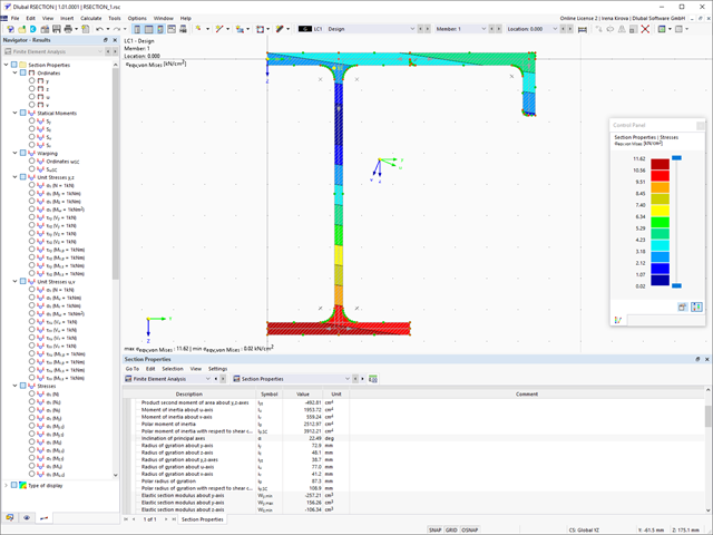
Podczas wymiarowania zgodnie z EN 1993-1-3, możliwe jest przedstawienie graficzne postaci własnej wyboczenia dystorsyjnego przekroju oraz dla przekrojów RSECTION.
Kształt postaci własnej można również wyprowadzić w RSECTION 1 dla przekrojów z biblioteki.
- 002317
- Ogólne informacje
- Projektowanie konstrukcji stalowych RFEM 6
- Projektowanie konstrukcji stalowych RSTAB 9
- Obliczanie ugięć i porównanie z normatywnymi lub ręcznie dostosowanymi wartościami granicznymi
- Uwzględnienie wygięcia wstępnego w analizie ugięcia
- W zależności od typu sytuacji obliczeniowej możliwe są różne wartości graniczne
- Ręczne dostosowywanie długości odniesienia i segmentacji według kierunku
- Obliczanie ugięć w odniesieniu do konstrukcji początkowej lub do konstrukcji odkształconej
- Dalsze szczegółowe obliczenia w zależności od wybranej normy obliczeniowej (np. ograniczenie oddychania środnika zgodnie z EN 1993-2)
- Graficzne wyświetlanie wyników zintegrowane z RFEM/RSTAB; na przykład stopień wykorzystania wartości granicznej, odkształcenie lub ugięcie
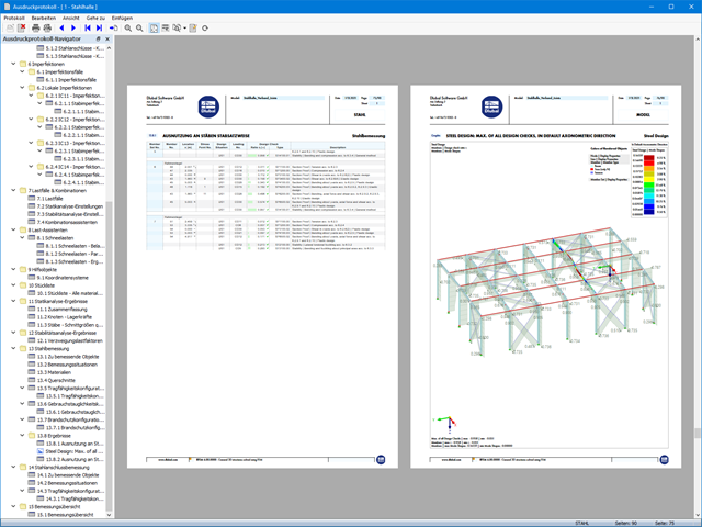
- Pełna integracja wyników z protokołem wydruku programu RFEM/RSTAB

- 002318
- Ogólne informacje
- Projektowanie konstrukcji stalowych RFEM 6
- Projektowanie konstrukcji stalowych RSTAB 9
W programie RFEM/RSTAB istnieje możliwość wygenerowania, a następnie obliczenia kombinacji obciążeń lub wyników wymaganych dla stanu granicznego użytkowalności. Sytuacje obliczeniowe można wybrać do analizy ugięć w rozszerzeniu Projektowanie konstrukcji stalowych. Obliczone wartości odkształceń są odpowiednio określane w każdym miejscu pręta, w zależności od określonego wygięcia wstępnego i układu odniesienia. Na koniec można porównać te wartości odkształceń z wartościami granicznymi.
Czy wiecie, że...? Wartość graniczną deformacji można określić indywidualnie dla każdego elementu konstrukcyjnego w Konfiguracja stanu granicznego użytkowalności. Jako dopuszczalną wartość graniczną należy zdefiniować maksymalne odkształcenie w zależności od długości odniesienia. Poprzez zdefiniowanie podpór obliczeniowych można podzielić komponenty na segmenty w celu automatycznego określenia odpowiedniej długości odniesienia dla każdego kierunku obliczeń.
W zależności od położenia przydzielonych podpór obliczeniowych, rozróżnienie między belkami i wspornikami jest dokonywane automatycznie, dzięki czemu można odpowiednio określić wartość graniczną.
- 002319
- Ogólne informacje
- Projektowanie konstrukcji stalowych RFEM 6
- Projektowanie konstrukcji stalowych RSTAB 9
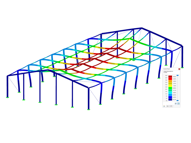
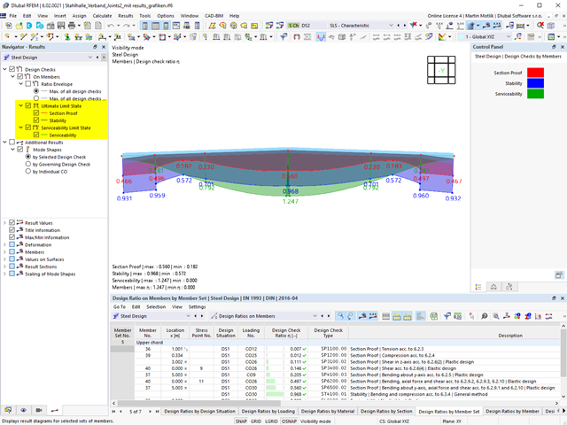
Zasady sprawdzania stanu granicznego użytkowalności można znaleźć w tabelach wyników w rozszerzeniu Projektowanie konstrukcji stalowych. Wyniki obliczeń można wyświetlić ze wszystkimi szczegółami w każdym miejscu obliczanych prętów. Ponadto dostępne są grafiki z wykresami wyników i stopni wykorzystania. Zapewnia to dobry przegląd sytuacji.
Wszystkie tabele wyników i grafiki można również zintegrować z globalnym protokołem wydruku programu RFEM/RSTAB jako część wyników wymiarowania stali. Dzięki temu można wyświetlać i dokumentować odkształcenia całej konstrukcji w ramach funkcji programu RFEM/RSTAB, niezależnie od rozszerzenia.
- 002320
- Ogólne informacje
- Projektowanie konstrukcji stalowych RFEM 6
- Projektowanie konstrukcji stalowych RSTAB 9
- Ręczne określenie temperatury krytycznej elementu lub automatyczne określenie temperatury elementu przez żądany czas
- Szeroki wybór krzywych pożaru: standardowa krzywa temperatura-czas, krzywa pożaru zewnętrznego, krzywa węglowodorów
- Ręczne dostosowywanie istotnych współczynników do określania temperatury stali
- Uwzględnienie cynkowania ogniowego elementów konstrukcyjnych przy określaniu temperatury stali
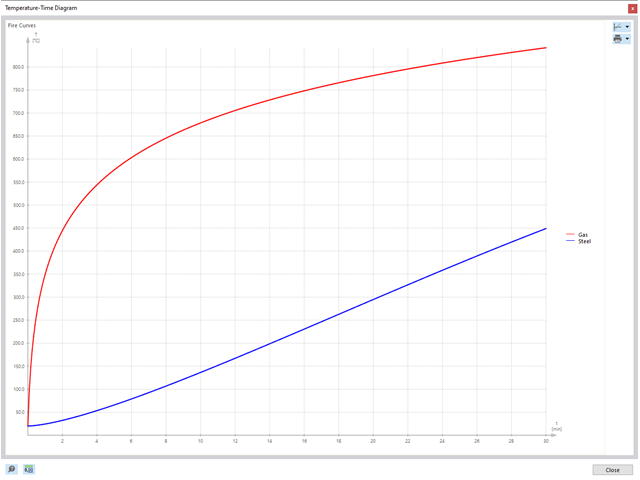
- Wyniki wykresu temperatura-czas dla temperatury gazu i stali
- Podczas określania temperatury można uwzględnić okładzinę ogniochronną w postaci obrysu lub okładziny skrzynkowej wykonanej z materiałów niezależnych od temperatury
- Wymiarowanie prętów ze stali węglowej lub nierdzewnej
- Obliczenia przekrojów i analiza stateczności (metoda prętów zastępczych) zgodnie z EN 1993-1-2, rozdz. 4.2.3
- Obliczenia przekrojów klasy 4 zgodnie z EN 1993-1-2, Załącznik E.
- 002321
- Ogólne informacje
- Projektowanie konstrukcji stalowych RFEM 6
- Projektowanie konstrukcji stalowych RSTAB 9
Programy do analizy statyczno-wytrzymałościowej RFEM/RSTAB oferują szereg zautomatyzowanych funkcji, które ułatwiają codzienną pracę. Jednym z nich jest automatyczne generowanie kombinacji obciążeń i wyników dla wyjątkowej sytuacji obliczeniowej w obliczeniach odporności ogniowej. Pręty, które mają zostać zwymiarowane wraz z odpowiednimi siłami wewnętrznymi, są importowane bezpośrednio z programu RFEM/RSTAB. Nie musisz'robić nic więcej. Program zachował również wszystkie informacje o materiale i przekroju.
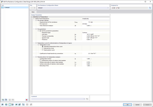
Poprzez przypisanie konfiguracji odporności ogniowej do obliczanych prętów, użytkownik definiuje parametry istotne dla obliczeń odporności ogniowej. Tutaj można ręcznie określić krytyczną temperaturę stali w czasie projektowania. Temperaturę wyznaczaną przez program można określić automatycznie dla określonego czasu trwania pożaru. Do wyboru dostępne są różne krzywe temperatury pożaru i środki ochrony przeciwpożarowej. Można również wprowadzić dalsze szczegółowe ustawienia, takie jak zdefiniowanie ekspozycji na ogień ze wszystkich stron lub z trzech stron
- 002322
- Ogólne informacje
- Projektowanie konstrukcji stalowych RFEM 6
- Projektowanie konstrukcji stalowych RSTAB 9
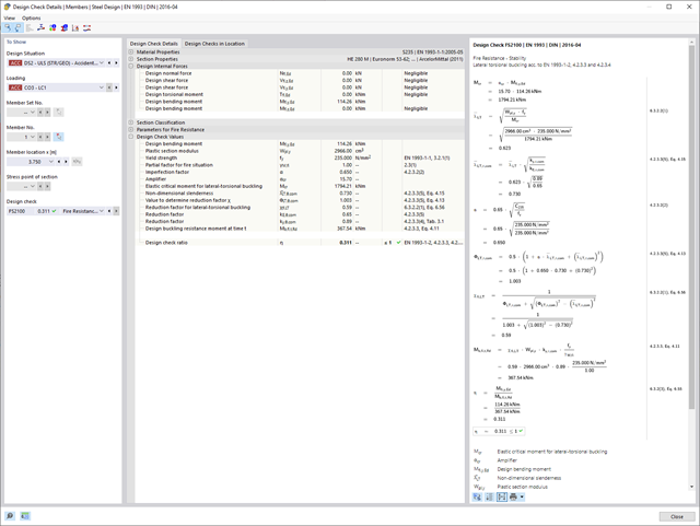
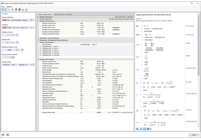
Weryfikacje wybranych prętów są przeprowadzane z uwzględnieniem decydującej temperatury elementu. W rozszerzeniu Projektowanie konstrukcji stalowych można przeprowadzić obliczenia przekrojów i analizy stateczności zgodnie z EN 1993-1-2, sekcja 4.2.3. Wszystkie niezbędne współczynniki i współczynniki redukcyjne są odpowiednio zapisywane i uwzględniane przy określaniu nośności.
Długości efektywne dla obliczeń pręta zastępczego są pobierane bezpośrednio z danych dotyczących wytrzymałości. Nie ma potrzeby'wprowadzania ich ponownie.
W każdym obliczeniu najpierw należy przeprowadzić klasyfikację przekroju. W przypadku przekrojów klasy 4 obliczenia są przeprowadzane automatycznie zgodnie z normą EN 1993-1-2, Załącznik E.
- 002323
- Ogólne informacje
- Projektowanie konstrukcji stalowych RFEM 6
- Projektowanie konstrukcji stalowych RSTAB 9
Po zakończeniu obliczeń, Dlubal Software przedstawia w przejrzysty sposób analizę odporności ogniowej wraz ze wszystkimi szczegółami wyników. Dzięki temu wyniki są zrozumiałe. Ponadto wyniki zawierają również wszystkie parametry wymagane do określenia temperatury elementu w czasie projektowania.
Rozkład temperatury w elemencie konstrukcyjnym można również ocenić za pomocą wykresu temperatura-czas.
Wszystkie tabele i grafiki wyników, w tym wyniki obliczeń stanu granicznego nośności i użytkowalności, można zintegrować z globalnym protokołem wydruku programu RFEM/RSTAB jako część wyników obliczeń konstrukcji stalowej.

- 002324
- Ogólne informacje
- Projektowanie konstrukcji stalowych RFEM 6
- Projektowanie konstrukcji stalowych RSTAB 9
W przypadku obliczeń zgodnie z Eurokodem 3 parametry załączników krajowych (NA) są zintegrowane dla następujących krajów:
-
 DIN EN 1993-1-1/NA:2020-11 (Niemcy)
 -
 ÖNORM EN 1993-1-1/NA:2015-12 (Austria)
 -
 SN EN 1993-1-1/NA:2016-07 (Szwajcaria)
 -
 BDS EN 1993-1-1/NA:2015-10 (Bułgaria)
 -
 BS EN 1993-1-1/NA:2016-07 (Wielka Brytania)
 -
 CEN EN 1993-1-1/2015-06 (Unia Europejska)
 -
 CYS EN 1993-1-1/NA:2015-07 (Cypr)
 -
 CZE EN 1993-1-1/NA:2016-06 (Republika Czeska)
 -
 DS EN 1993-1-1/NA:2015-07 (Dania)
 -
 ELOT EN 1993-1-1/NA:2017-01 (Grecja)
 -
 EVS EN 1993-1-1/NA:2015-08 (Estonia)
 -
 HRN EN 1993-1-1/NA:2016-03 (Chorwacja)
 -
 I S. EN 1993-1-1/NA:2016-03 (Irlandia)
 -
 ILNAS EN 1993-1-1/NA:2015-06 (Luksemburg)
 -
 IST EN 1993-1-1/NA:2015-11 (Islandia)
 -
 LST EN 1993-1-1/NA:2017-01 (Litwa)
 -
 LVS EN 1993-1-1/NA:2015-10 (Łotwa)
 -
 MS EN 1993-1-1/NA:2010-01 (Malezja)
 -
 MSZ EN 1993-1-1/NA:2015-11 (Węgry)
 -
 NBN EN 1993-1-1/NA:2015-07 (Belgia)
 -
 NEN EN 1993-1-1/NA:2016-12 (Holandia)
 -
 NF EN 1993-1-1/NA:2016-02 (Francja)
 -
 NP EN 1993-1-1/NA:2009-03 (Portugalia)
 -
 NS EN 1993-1-1/NA:2015-09 (Norwegia)
 -
 PN EN 1993-1-1/NA:2015-08 (Polska)
 -
 SFS EN 1993-1-1/NA:2015-08 (Finlandia)
 -
 SIST EN 1993-1-1/NA:2016-09 (Słowenia)
 -
 SR EN 1993-1-1/NA:2016-04 (Rumunia)
 -
 SS EN 1993-1-1/NA:2019-05 (Singapur)
 -
 SS EN 1993-1-1/NA:2015-06 (Szwecja)
 -
 STN EN 1993-1-1/NA:2015-10 (Słowacja)
 -
 TKP EN 1993-1-1/NA:2015-04 (Białoruś)
 -
 UNE EN 1993-1-1/NA:2016-02 (Hiszpania)
 -
 UNI EN 1993-1-1/NA:2015-08 (Włochy)
- 002325
- Ogólne informacje
- Projektowanie konstrukcji stalowych RFEM 6
- Projektowanie konstrukcji stalowych RSTAB 9
Należy przeprowadzić obliczenia odporności ogniowej ze zredukowaną nośnością na podstawie temperatury elementu, wyznaczonej automatycznie w czasie projektowania. Można to określić automatycznie na podstawie różnych krzywych temperatury w programie (standardowa krzywa temperatura-czas, krzywa pożaru zewnętrznego, krzywa węglowodorów). W przypadku innych typów określania temperatury można również ręcznie określić temperaturę, która zostanie zastosowana w obliczeniach. Można to na przykład określić zgodnie z parametryczną krzywą temperatura-czas z normy DIN EN 1991-1-2 lub z protokołu ochrony przeciwpożarowej.
- 002326
- Ogólne informacje
- Projektowanie konstrukcji stalowych RFEM 6
- Projektowanie konstrukcji stalowych RSTAB 9
Temperatura elementu, która ma być zastosowana w czasie projektowania, jest określana automatycznie. Współczynniki używane do określania temperatury można dostosowywać. Na tym etapie najlepiej jest również wybrać cynkowanie ogniowe. Zgodnie z wytyczną DASt 027 „Wyznaczanie temperatury elementów ze stali ocynkowanej ogniowo na wypadek pożaru“, stosowana jest niższa emisyjność powierzchni stalowej, aż do osiągnięcia określonej temperatury granicznej. Ogólnie rzecz biorąc, daje to niższą temperaturę, a tym samym bardziej korzystne obliczenia odporności ogniowej.
- 002327
- Ogólne informacje
- Projektowanie konstrukcji stalowych RFEM 6
- Projektowanie konstrukcji stalowych RSTAB 9
Na podstawie danych wejściowych można automatycznie określić decydującą temperaturę elementu w momencie przeprowadzania analizy. W takim przypadku można szczegółowo prześledzić krzywą temperatury w funkcji czasuwykres temperatura-czas.
- 002328
- Ogólne informacje
- Projektowanie konstrukcji stalowych RFEM 6
- Projektowanie konstrukcji stalowych RSTAB 9
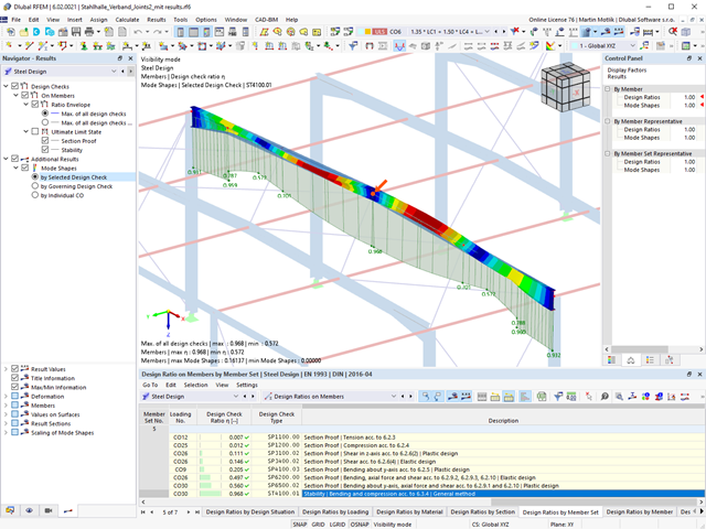
Czy przejrzysty układ jest dla Ciebie ważny? Program zapewnia przejrzysty przegląd wszystkich przeprowadzonych kontroli obliczeń dla danej normy obliczeniowej. Dla każdej kontroli obliczeń konieczne jest określenie kryterium obliczeniowego. Dostępne są również szczegóły obliczeń, w tym wartości początkowe, wyniki pośrednie i wyniki końcowe. W tym miejscu znajduje się również okno informacyjne, w którym szczegółowo przedstawiony jest przebieg obliczeń wraz z zastosowanymi wzorami, standardowymi źródłami i wynikami.
- 002329
- Ogólne informacje
- Projektowanie konstrukcji stalowych RFEM 6
- Projektowanie konstrukcji stalowych RSTAB 9
Wyniki obliczeń można znaleźć bezpośrednio w rozszerzeniu Projektowanie konstrukcji stalowych. Są one tam dostępne w formie tabelarycznej. Rozkład stopni wykorzystania można również wyświetlić graficznie. Zarówno w tabeli, jak i w postaci graficznej dostępne są liczne opcje filtrowania. Dzięki temu można wyświetlać żądane warunki projektowe według stanu granicznego lub typu obliczeń.
- 002330
- Ogólne informacje
- Projektowanie konstrukcji stalowych RFEM 6
- Projektowanie konstrukcji stalowych RSTAB 9
W zależności od kierunku można indywidualnie zdefiniować wszystkie długości odniesienia, które muszą zostać uwzględnione podczas obliczeń wartości granicznej ugięcia, a także które segmenty mają zostać sprawdzone. W tym celu należy zdefiniować podpory obliczeniowe w węzłach pośrednich pręta i przydzielić je do odpowiedniego kierunku na potrzeby analizy odkształceń. W ten sposób tworzone są segmenty, w których można zdefiniować wygięcie wstępne dla każdego kierunku i segmentu.
- 002331
- Ogólne informacje
- Projektowanie konstrukcji stalowych RFEM 6
- Projektowanie konstrukcji stalowych RSTAB 9
Rozszerzenie Projektowanie konstrukcji stalowych pomaga między innymi w wymiarowaniu ogólnych przekrojów, które nie są wstępnie zdefiniowane w bibliotece przekrojów. W tym celu należy utworzyć przekrój w programie RSECTION, a następnie zaimportować go do RFEM/RSTAB. W zależności od zastosowanej normy projektowej dostępne są różne formaty obliczeń. Jedną z nich jest na przykład analiza równoważnych naprężeń. Masz licencję na RSECTION i Przekroje efektywne? Następnie można przeprowadzić obliczenia z uwzględnieniem efektywnych właściwości przekrojów zgodnie z EN 1993-1-5.
- 002332
- Ogólne informacje
- Projektowanie konstrukcji stalowych RFEM 6
- Projektowanie konstrukcji stalowych RSTAB 9
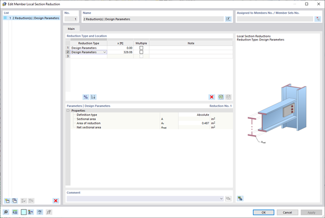
Należy pamiętać, że w przypadku łączenia elementów obciążonych rozciąganiem za pomocą połączeń śrubowych, w obliczeniach w stanie granicznym nośności należy uwzględnić redukcję przekroju ze względu na otwory na śruby. Ale bez obaw, można to łatwo zrobić w programie. W rozszerzeniu Projektowanie konstrukcji stalowych można wprowadzić lokalną redukcję przekroju pręta - i to wszystko. Redukcję przekroju można wprowadzić jako wartość bezwzględną lub jako procent całkowitej powierzchni we wszystkich istotnych miejscach.
- 002333
- Ogólne informacje
- Projektowanie konstrukcji stalowych RFEM 6
- Projektowanie konstrukcji stalowych RSTAB 9
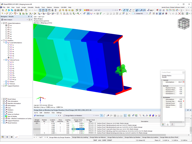
Rozszerzenie Skręcanie skrępowane (7 stopni swobody) oferuje szereg nowych opcji. W programach RFEM i RSTAB można na przykład przeprowadzić obliczenia konstrukcji prętowych z uwzględnieniem deplanacji przekroju. Wypadkowe siły wewnętrzne (N, Vu, Vv, Mt,pri, Mt,sec, Mu, Mv, Mω) można uwzględnić w analizie naprężeń równoważnych dla konstrukcji stalowych. Powiadomienia Funkcja ta nie jest obecnie dostępna dla norm projektowych AISC 360-16 i GB 50017.
- 002334
- Ogólne informacje
- Projektowanie konstrukcji stalowych RFEM 6
- Projektowanie konstrukcji stalowych RSTAB 9
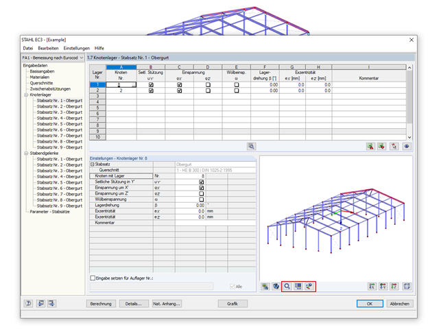
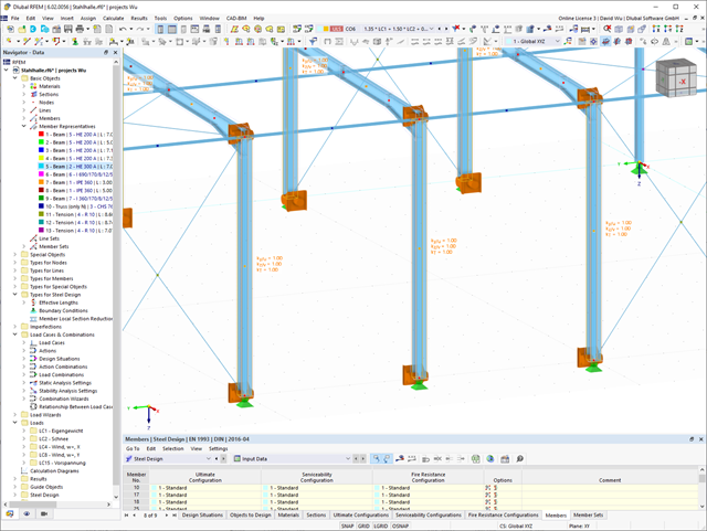
Czy chcesz przeprowadzić analizę stateczności w rozszerzeniu Projektowanie konstrukcji stalowych? W takim przypadku należy bezwzględnie zdefiniować długości efektywne. W tym celu w oknie wprowadzania danych należy zdefiniować podpory węzłowe i współczynniki długości efektywnej. W celu ułatwienia dokumentacji i kontroli wprowadzonych danych można również wyświetlić graficznie podpory węzłowe i powstałe w ten sposób segmenty wraz z odpowiednim współczynnikiem długości efektywnej w oknie roboczym programu RFEM/RSTAB.
- 002335
- Ogólne informacje
- Projektowanie konstrukcji stalowych RFEM 6
- Projektowanie konstrukcji stalowych RSTAB 9
Czy do określenia współczynnika obciążenia krytycznego do analizy stateczności użyto solwera wartości własnych rozszerzenia? W ten sposób można wyświetlić decydujący kształt drgań własnych projektowanego obiektu. Na potrzeby analizy zwichrzenia dostępny jest solwer wartości własnych, w zależności od zastosowanej normy obliczeniowej. W przypadku metody ogólnej zgodnie z EN 1993-1-1, 6.3.4 można również użyć wewnętrznego solwera wartości własnych.

- 002232
- Ogólne informacje
- Optymalizacja i koszty | Szacowanie emisji CO2 RFEM 6
- Optymalizacja i koszty | Szacowanie emisji CO2 RSTAB 9
Możesz być pewien, że koszty są ważnym czynnikiem w planowaniu konstrukcyjnym każdego projektu. Należy również przestrzegać przepisów dotyczących szacowania emisji. Dwuczęściowe rozszerzenie Optymalizacja i koszty/Szacowanie emisji CO2 ułatwia odnalezienie się w gąszczu norm i opcji. Wykorzystuje technologię sztucznej inteligencji (AI) optymalizacji rojem cząstek (PSO) w celu znalezienia odpowiednich parametrów dla sparametryzowanych modeli i bloków, które zagwarantują zgodność ze zwykłymi kryteriami optymalizacji. Ponadto, rozszerzenie oszacowuje koszty modelu lub emisję CO2 poprzez określenie kosztów jednostkowych lub emisji jednostkowej dla materiałów zdefiniowanych w modelu konstrukcyjnym. Dzięki temu rozszerzeniu jesteś po bezpiecznej stronie.

Dzięki rozszerzeniu Analiza historii czasowej (TDA) można uwzględnić zmienne w czasie zachowanie materiału w przypadku prętów i powierzchni. Długotrwałe efekty, takie jak pełzanie, skurcz i starzenie, mogą wpływać na rozkład sił wewnętrznych, w zależności od konstrukcji. Darauf bereiten Sie sich mit diesem Add-On optimal vor.
Dla każdego przypadku obciążenia można wyświetlić odkształcenia w czasie końcowym.
Wyniki te są również dokumentowane w protokole wydruku programów RFEM i RSTAB. Zawartość protokołu i jego zakres można wybrać specjalnie dla poszczególnych warunków projektowych.