Office Building Palmovka Open Park IV - Arch Hall, Czech Republic
Customer Project
The arched hall includes a 72 ft x177 ft rectangular floor plan, 33 ft height and 66 ft roof radius. The structure houses large offices with additional storage space available.
Structural Analysis |
Ing. Pavel Korejčík Ing. Jan Seifert
KONSTAT s.r.o. |
Architectural Design | Aulík Fišer Architekti s.r.o. |
Model Parameters
Model
The large hall building is comprised of a steel arched roof supported on steel columns which further tie into the reinforced concrete foundation.
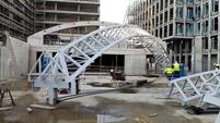
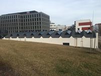
The steel structure is entirely covered at both the ceiling and wall locations. Only the steel frame tie rods and continuous purlins in the place of skylights are visible. Portions of the original structure are still utilized throughout the building but do not serve any structural capacity. This includes specifically the timber arched trusses with tie rods and struts, steel lattice columns and roof skylights.
Structure
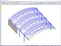
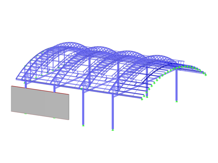
The main structural components include ten steel frames 32.5 ft in height, spanning 79.6 ft, spaced 18 ft on-center. The frames are laterally restrained and consist of columns, tie rods and arched lattice rafters. Geometrically, the steel frames are asymmetrical due to the various column distances from the arch axis.The steel frame columns are reinforced HEA sections, the tie rods are flat bars and the frame rafters are round tubes. The frame rafter includes a triangular lattice arch truss (one top chord and two bottom chords), struts (crossbeams) and diagonal bracing between the bottom chords. The trusses further connect at the base to the reinforced HEA columns. Purlins constructed from IPE sections (welded I-beams) connect to the underside of the arch trusses.
Project Location
Prague, Palmovka, Czech RepublicKeywords
Steel structure Arched hall Office building
Write Comment...
Write Comment...
Contact us
Do you have questions or need advice?
Contact our free e-mail, chat, or forum support or find various suggested solutions and useful tips on our FAQ page.
Recommended Events
Videos
Models to Download
Knowledge Base Articles

New
Design of a welded truss
This technical article deals with the component and cross-section designs of a welded truss in the ultimate limit state. Furthermore, the deformation analysis in the serviceability limit state is described.
Screenshots
Product Features Articles

Material Database with Steels According to the Australian Standard AS/NZS 4600:2005
The material database in RFEM, RSTAB and SHAPE-THIN contains steels according to the Australian standard AS/NZS 4600:2005.Frequently Asked Questions (FAQ)
- I would like to perform a stability analysis of the upper flange in a long truss. What is the best way to proceed?
- Which cross-sections can I design with the "RF‑/STEEL Cold-Formed Sections" add-on module?
- What is the difference between the RF‑/STEEL and RF‑/STEEL EC3 add-on modules?
- I perform a stability analysis of a beam for lateral-torsional buckling. Why is the modified reduction factor χLT,mod used in the design according to DIN EN 1993‑1‑1, 6.3.3 Method 2? Is it possible to deactivate this?
- I need to define different types of lateral intermediate restrains for a single element in RF-/STEEL EC3. Is this possible?
- I compare the flexural buckling design according to the equivalent member method and the internal forces according to the linear static analysis with the stress calculation according to the second-order analysis including imperfections. The differences are very large. What is the reason?
- Is it possible to design member groups using the EC3 add-on module?
- Is it possible to use the RF‑/STEEL EC3 add-on module itself to specify the internal forces, for example, from another calculation or program?
- How can I set the required time t for the fire resistance design in RF‑/STEEL EC3?
- Why are the equivalent member designs grayed out in the Stability tab when activating the plastic designs by using the partial internal force method (RF‑/STEEL Plasticity)?