This Knowledge Base article discusses different methods for a stability analysis (Image 01) provided in EN 1993-1-1:2005 [1] and their application in the RFEM 6 program. The example used to demonstrate these methods (Image 01) is based on the work of E. Chladný and M. Štujberová [2] provided at the end of this article under “References”. It is important to note that lateral-torsional buckling is excluded in this example and the verifying procedure is explained in the following paragraph.
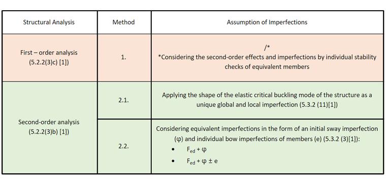
In line with the above-mentioned article [1], a stability design check and a geometrically linear structural analysis for the numerical example of interest are considered as the first analysis approach. Next, a structural analysis according to the second-order analysis is discussed.
In this case, the shape of the elastic critical buckling mode of a structure is first introduced as a unique global and local imperfection. Later, equivalent imperfections in the form of an initial sway imperfection (φ) and individual bow imperfections of members (e) are considered. Finally, the results are analyzed and assessed in the same way as in [2].
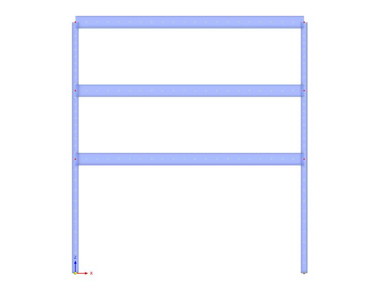
As already mentioned, these different methods are applied to a numerical example and the results are examined and compared. The structure of interest is a steel frame shown in Image 02. The actions on the structure and the sections used for beams and columns are also shown in the image.
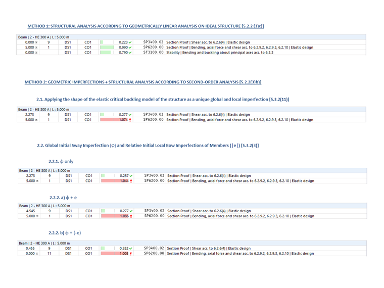
1. Structural Analysis According to Geometrically Linear Analysis on Ideal Structure
The method given in 5.2.2 (3)c) of EN 1993-1-1:2005 [1] implies that it is possible to perform geometrically linear analysis and consider the second-order effects and imperfections by the individual stability checks of equivalent members according to 6.3 [1]. For this purpose, it is necessary to use appropriate buckling lengths in compliance with the global buckling mode of the structure, based on the strength format of the European buckling curves with the reduction factor χ1.
To do this in RFEM 6, make sure that the “Structure Stability” add-on is activated in addition to the “Steel Design” add-on. This will allow you to perform the stability check and import effective lengths from the stability analysis (Image 03). More about this topic can be found in the Knowledge Base article:
Determining Effective Lengths in RFEM 6
.
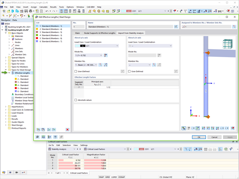
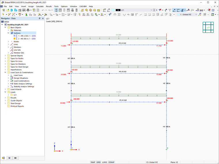
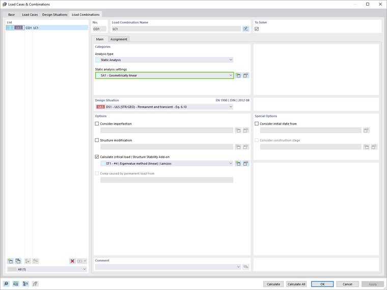
Please note that if you want to perform the structural analysis according to the geometrically linear analysis, it is necessary to set the “Geometrically linear” analysis type in the Load Cases & Combinations to be calculated (Image 04). By doing so, the imperfections and second-order effects are not considered in the calculation of internal forces, but rather in the stability analysis by using the factor for buckling length due to the global frame behavior.
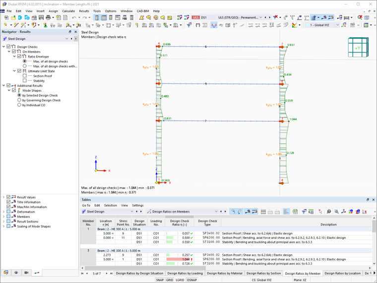
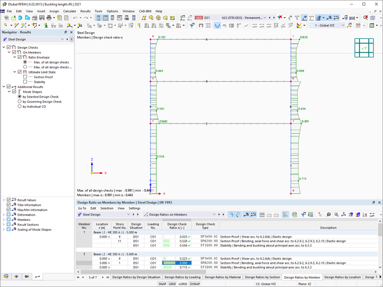
The results of the “Steel Design” add-on using this method are shown in Image 05.
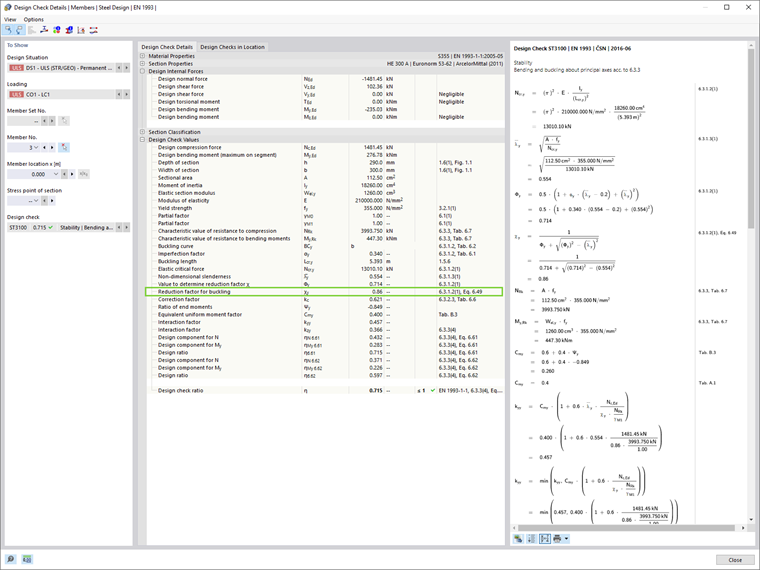
The reduction factor for buckling χ1 in RFEM 6 is calculated in line with the strength format of the European buckling curves. This can be seen easily in the design check details of the individual members (Image 06), which can be displayed by clicking the “Design Check Details” button in the Steel Design Results table.
2. Second–Order Analysis and Consideration of Geometric Imperfections
In general, critical load factors lower than 10 imply that the internal forces and moments should be calculated to allow for the second-order effects. Geometric imperfections should also be considered, and the approaches presented in this article are as follows:
- Applying the shape of an elastic critical buckling mode of the structure as a unique global and local imperfection (5.3.2.11 [1])
- Considering the equivalent imperfections in the form of an initial sway imperfection and individual bow imperfections of members (5.3.2.3 [1])
2.1. Applying Shape of Elastic Critical Buckling Mode of Structure as Unique Global and Local Imperfection
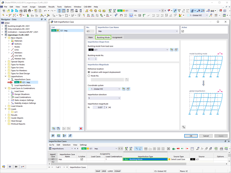
The approach introduced in 5.3.2.11 [1] suggests that the shape of the elastic critical buckling mode of the structure may be applied as a unique global and local imperfection. To do this in RFEM 6, it is necessary to create an imperfection case with the “Buckling Mode” imperfection type.
The first buckling mode of the structure was calculated in the stability analysis described in the previous chapter, and it can be used now to define the imperfection case as shown in Image 07. The second-order analysis settings concerning the imperfection effects in the buckling mode shape are shown in Image 08.

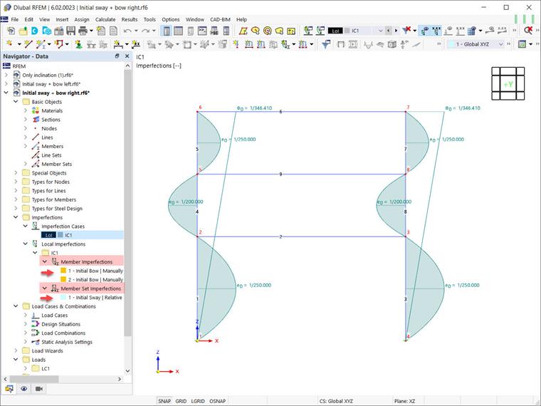
2.2. Considering Equivalent Imperfections in Form of Initial Sway Imperfection (φ) and Individual Bow Imperfections of Members (e)
According to the approach presented in 5.3.2 (3)[1], the effect of imperfections for the frames susceptible to buckling in a sway mode should be applied in the frame analysis using the equivalent imperfection in the form of an initial sway imperfection and individual bow imperfections of members.
2.2.1. Initial Sway Imperfection (φ)
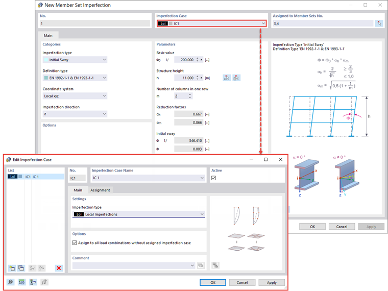
First, the analysis will be performed by considering an equivalent imperfection in the form of an initial sway imperfection only. In RFEM 6, a global initial sway imperfection is introduced as "Member Set Imperfection", as shown in Image 09.
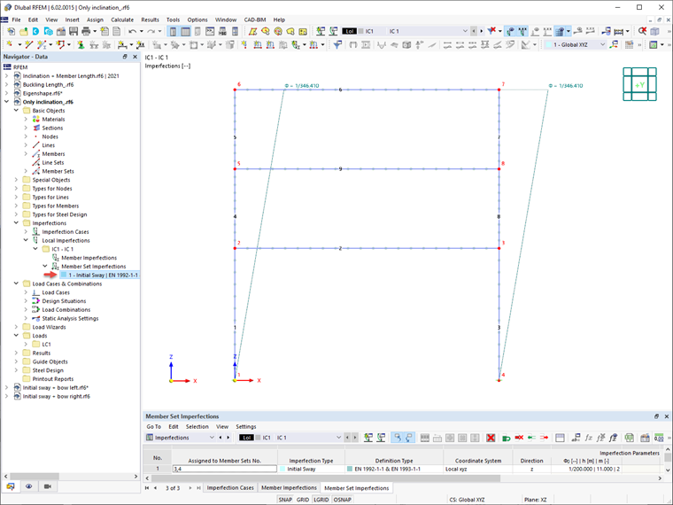
In this way, the initial sway is defined, as shown in Image 10.
2.2.2. Initial Sway Imperfection (φ) and Individual Bow Imperfections of Members (±e)
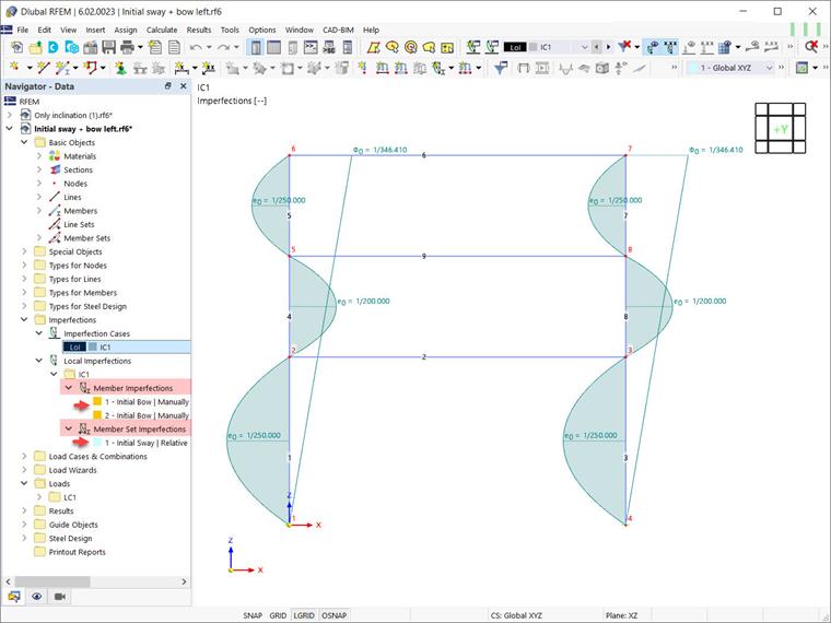
In addition to the global sway imperfections, the relative initial local bow imperfections of members should be considered. In RFEM 6, they can be defined as member imperfections with the “Initial Bow” type. In this example, such imperfections are considered once for the positive global X direction (+e), and once for the negative direction (-e). This is shown in Images 11 and 12, respectively.
Summary of Results
A comparison of the different methods (Image 13) leads to the conclusion that the use of the strength format of the European buckling curves with the reduction factor χ1 (Method 1) gives less conservative results than the direct design method (Method 2), which considers the imperfections and the structural analysis according to the second-order theory. The results also show that the differences between both approaches considering the imperfection effects in Method 2 (that is, 5.3.2(3) and 5.3.2(11)) are rather small for rectangular continuous frames.
At this point, we can refer to 5.3.2 (6) of EN 1993-1-1:2005 [1] which suggests that local bow imperfections may be neglected when performing the global analysis for determining the end forces and end moments to be used in the member checks according to 6.3.
Thus, the imperfections can only be introduced in the form of a global sway imperfection in this numerical example, and the stability checks of equivalent members according to 6.3 [1] can be performed. Given the second-order analysis and the consideration of the global frame behavior, this verification should be based on the buckling length equal to the member length, as provided in 5.2.2 (7) b of EN 1993-1-1:2005 [1]. Finally, the results are shown in Image 14.