Description
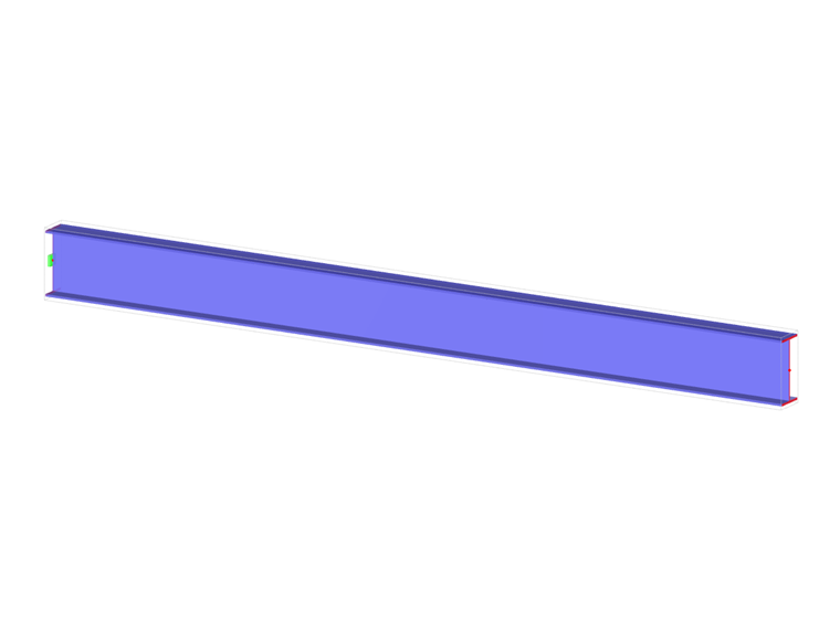
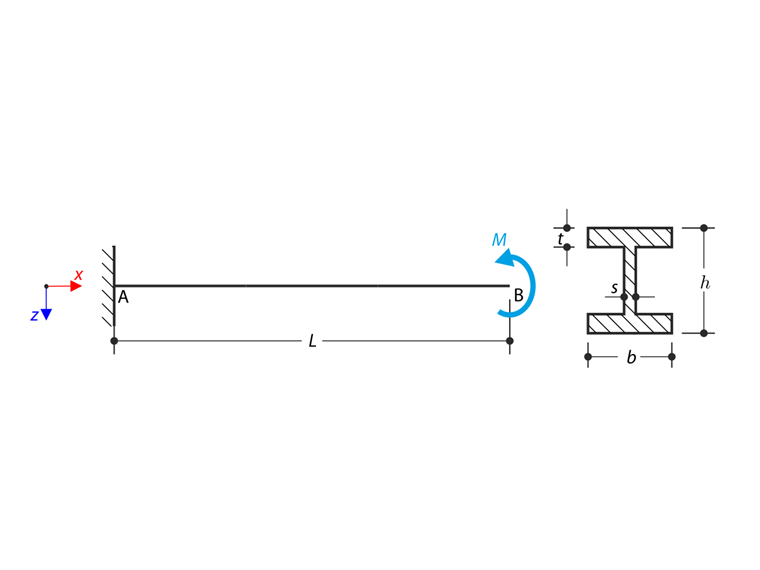
A cantilever of I-profile is supported on the left end (x=0) and it is loaded by the torque M according to the following sketch. The aim of this example is to compare the fixed support with the fork support and to investigate the behaviour of some representative quantities. The comparison with the solution by means of plates is also made. The verification example is based on the example introduced by Gensichen and Lumpe (see the reference). Small deformations are considered and the self-weight is neglected. Determine the rotation in the half of the cantilever φx(L/2) and in case of the member entity with warping determine the values of the primary torsional moment MTpri, the secondary torsional moment MTsec and the warping moment Mω both on the left end (point A) and on the right end (point B). The problem is described by the following set of parameters.
| Material | Steel | Modulus of Elasticity | E | 210000.000 | MPa |
| Shear Modulus | G | 81000.000 | MPa | ||
| Geometry | Cantilever | Length | L | 5.000 | m |
| Cross-section | Height | h | 400.000 | mm | |
| Width | b | 180.000 | mm | ||
| Web Thickness | s | 10.000 | mm | ||
| Flange Thickness | t | 14.000 | mm | ||
| Load | Moment | M | 1.000 | kNm | |
Analytical Solution
When considering member calculation with warping the total torsional moment MT is divided between the the primary torsional moment MTpri and the secondary torsional moment MTsec.
The equation can be expressed as follows:
This is the complete differential equation of the torsion. It can be solved by the method of initial parameters and results into equations for the rotation φx, relative twist φ'x and warping moment Mω, primary torsional moment MTpri and secondary torsional moment MTsec.
The warping is restrained, when the fixed support is considered. Boundary conditions in this case are: φ(0)=0, φ'(0)=0, MT(0)=M, Mω(L)=0.
When the fork support is considered, the warping is enabled and the boundary conditions are following: φ(0)=0,Mω(0)=0, MT(0)=M, Mω(L)=0.
Using those boundary conditions the rotation φ(x) results into well-known formula.
RFEM Settings
- Modeled in RFEM 5.05 and RFEM 6.01
- The element size is lFE= 0.025 m
- Isotropic linear elastic material model is used
- Kirchhoff plate bending theory is used
- Torsional Warping and Steel Design add-on is used in RFEM 6
Results
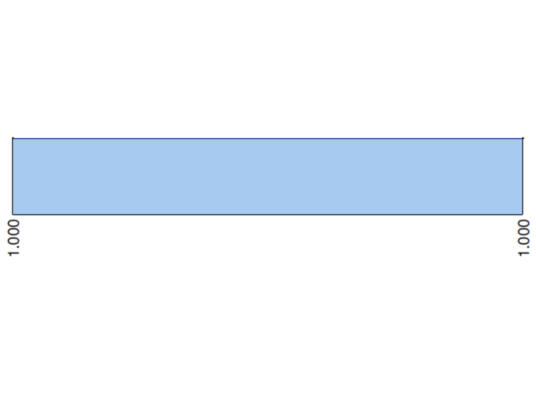
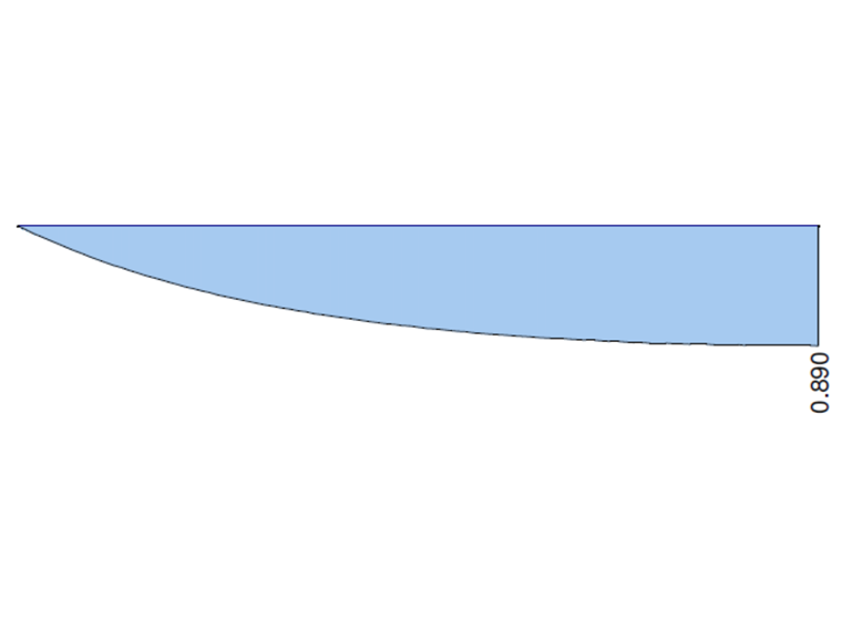
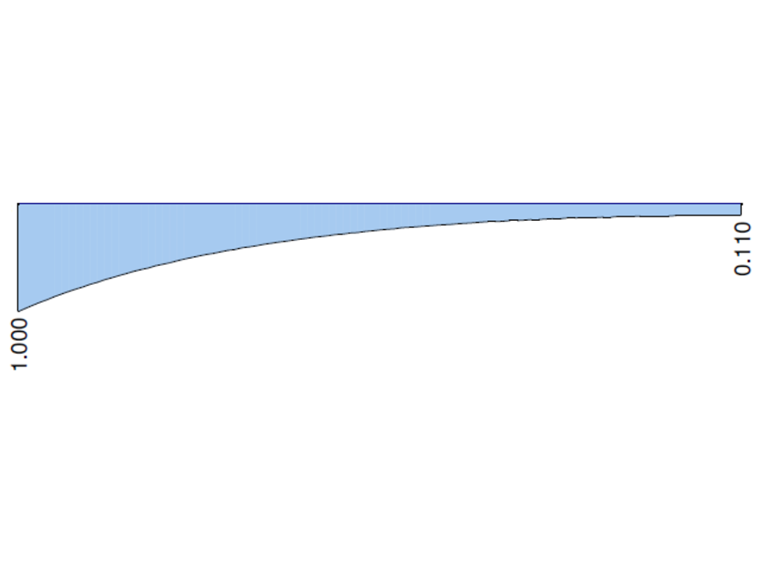
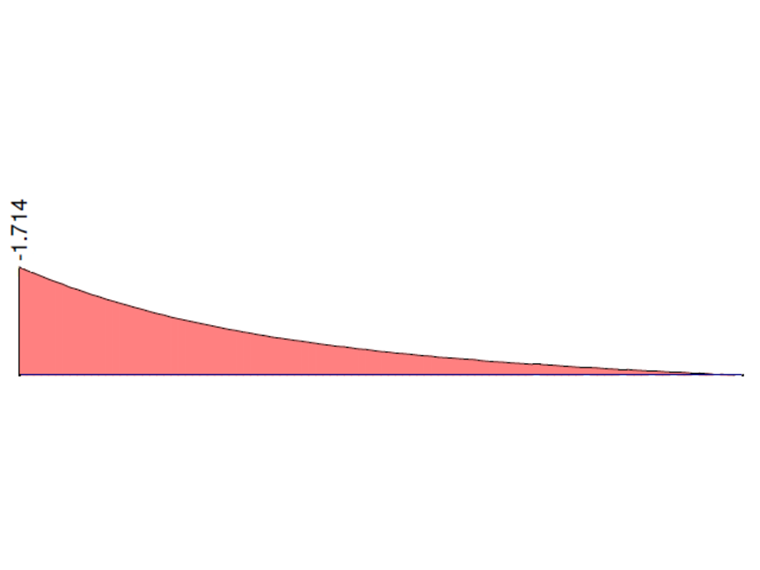
In the following graphs there are shown behaviours of the total torsional moment MT, the primary torsional moment MTpri, the secondary torsional moment MTsec and the warping moment Mω calculated in RFEM 6 and RFEM 5, RF-FE-LTB module, when the fixed support is considered. Values on the both ends of the cantilever are compared with the analytical solution and solution in ANSYS 13.
| Point A (x=0) | Analytical Solution | ANSYS 13 | Ratio | RFEM 6 | Ratio | RFEM RF-FE-LTB | Ratio |
| MTpri [kNm] | 0.000 | 0.008 | - | 0.000 | - | 0.000 | - |
| MTsec [kNm] | 1.000 | 0.992 | 0.992 | 1.000 | 1.000 | 1.000 | 1.000 |
| Mω [kNm] | -1.714 | -1.683 | 0.989 | -1.743 | 1.017 | -1.714 | 1.000 |
| Point B (x=L) | Analytical Solution | ANSYS 13 | Ratio | RFEM 6 | Ratio | RFEM RF-FE-LTB | Ratio |
| MTpri [kNm] | 0.890 | 0.893 | 1.003 | 0.869 | 0.976 | 0.890 | 1.000 |
| MTsec [kNm] | 0.110 | 0.107 | 0.973 | 0.131 | 1.191 | 0.110 | 1.000 |
| Mω [kNm] | 0.000 | 0.001 | - | 0.000 | - | 0.000 | - |
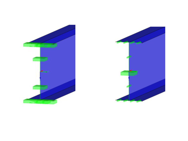
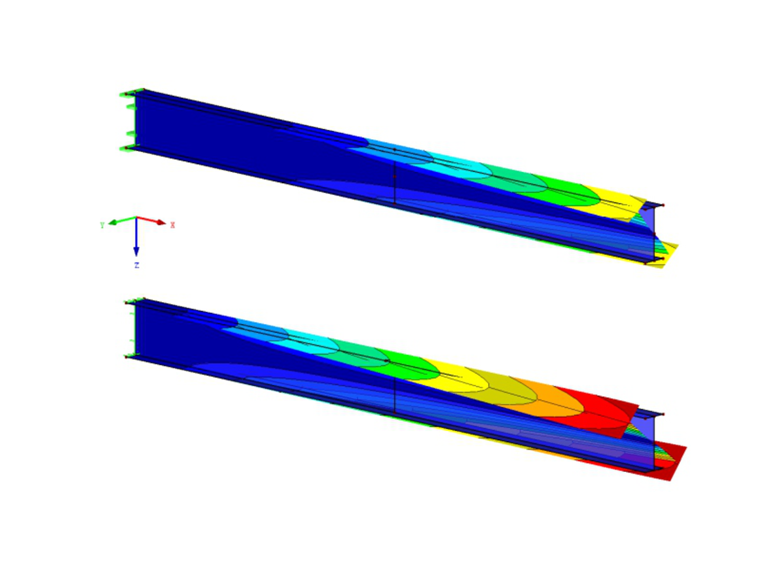
The calculated rotation round the x-axis can be compared with the results, when the fork support is considered and also with plate models, which take the warping naturally into the account. The rotation at the half length φ(L/2) is used due to the affected area in the nearby of the loading point in case of plate models. The definition of the fork support in case of the plate model is complicated, because the warping moment has to equal to the zero. This boundary condition can not be set directly in RFEM 5 / RFEM 6. Used approximation is shown in the following figure. The rotation round the x-axis is restrained on all edges of the support. Only the central node (on the axis) is fully fixed. In case of fixed support all the edges of the support are fixed.
| Support | Analytical Solution | ANSYS 13 | RFEM 6 (Member) | RFEM 6 (Plate) | |||
| φx(L/2) [mrad] | φx(L/2) [mrad] | Ratio [-] | φx(L/2) [mrad] | Ratio [-] | φx(L/2) [mrad] | Ratio [-] | |
| Fixed Support | 32.6 | 32.2 | 0.988 | 32.4 | 0.994 | 32.7 | 1.003 |
| Fork Support | 69.9 | 68.5 | 0.979 | 69.9 | 1.000 | 68.8 | 0.999 |
| Support | Analytical Solution | ANSYS 13 | RFEM 5, RF-FE-LTB (Member) | RFEM 5 (Plate) | |||
| φx(L/2) [mrad] | φx(L/2) [mrad] | Ratio [-] | φx(L/2) [mrad] | Ratio [-] | φx(L/2) [mrad] | Ratio [-] | |
| Fixed Support | 32.6 | 32.2 | 0.988 | 32.6 | 1.000 | 32.5 | 0.974 |
| Fork Support | 69.9 | 68.5 | 0.979 | 69.9 | 1.000 | 68.1 | 0.974 |
Remark 1: The solution with plate models is used as a demonstration of the warping effect. The relative error is caused also by the approximation of the fork support.
Remark 2: Numerical solution in ANSYS 13 was carried out by the company Designtec s.r.o. The quantities MTpri and $ MTsec are not the original results from ANSYS 13. They are calculated from the warping moment Mω. Thus they should no not be taken as entirely accurate values. Elements BEAM188 are used in ANSYS 13.