Saarschleife Lookout Tower, Germany
Customer Project
With a height of about 137.8 ft, the lookout tower offers a unique view over the landscape of the Saar-Hunsrück Nature Park, into the Saar Bow Valley and, if the visibility is clear, even as far as the Vosges Mountains. The tower is the highlight of the treetop trail with a length of 4,101 ft, which allows for walks up to 75.5 ft above the forest level.
Investor |
Erlebnis Akademie AGBad Kötzting, Germany www.eak-ag.de |
Architect |
Architekturbüro Josef Stöger stoeger-koelbl.de |
Planning, Structural Engineering, and Construction |
WIEHAG GmbH www.wiehag.com |
Structural Analysis of Foundations |
Ing.-Büro Wolf GmbH D-94036 Passau |
Model
The tower was designed in a semicircle to mirror the Saar Bow. The semicircular form was also chosen as an effective way to minimize the impact on the quartzite biotope.
The company WIEHAG GmbH was responsible for the planning, structural analysis, design, fabrication, and assembly of the tower. RSTAB software was used for the structural calculations.
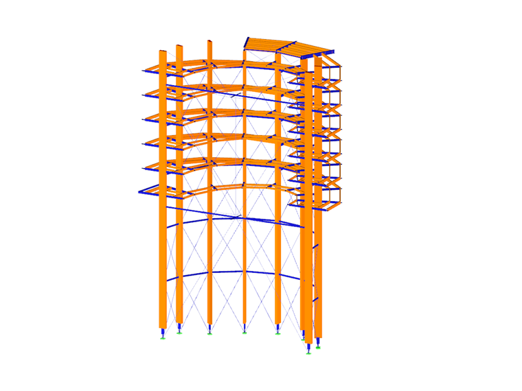
Structure
There are 9 straight glued-laminated beams arranged rotationally and symmetrically around the longitudinal axis of the tower. These are connected by 5 horizontal rings made of steel tubes. The steel tubes are rigidly connected to the main columns around the local z-axis to avoid lateral deflection of the columns out of the plane. There is a mesh of steel diagonals between the columns.
Another stiffening structure consisting of two suspended steel tubes and a stiffening cross is located between both edge columns.
The angle between the columns is 18° in the edge area and 24° in the other areas. The tower has a diameter of 40 ft, referred to the center of the glulam columns.
The tower can be accessed from the treetop trail at a height of about 65.6 ft. A helical ramp with a width of 8.2 ft is attached to the inside and outside of the columns and leads up to the viewing platform.
The platform is 19.7 ft wide and consists of steel cantilever beams, protruding to the outside and connected to the timber columns. On the cantilever beams, there are again timber stringers covered by the wooden floor.
Project Location
Write Comment...
Write Comment...
Contact Us
Do you have any further questions or need advice? Contact us via phone, email, chat or forum or find suggested solutions and useful tips on our FAQ page, available 24/7.

New
Saving Models as Blocks in RFEM 6
In RFEM 6 it is possible to save selected objects, as well as whole structures, as blocks and reuse them in other models. Three types of blocks can be distinguished: non-parameterized, parameterized, and dynamic blocks (via JavaScript). This article will focus on the first block type (non-parameterized).

New
Timber Design | Result Filter by Limit State
The design checks are available in a tabular form in the Timber Design add-on. The distribution of the design ratios can also be displayed graphically. There are extensive filter options available in the table as well as in the graphical output to display the desired design checks by a limit state or a design type.
-
How do I define a member as a cantilever and not as supported at both ends for serviceability or deflection design?
- I would like to export nodal support forces of several load cases, load combinations and result combinations into an Excel spreadsheet in RFEM 6. How should I proceed?
- Where can find the option to hide the defined types (for example, design supports or effective lengths)?
- How do I create a user-defined Design Situation with my own chosen load combinations?
- How can I neglect torsion in the steel and timber design?
- How do I perform stability analysis to determine the critical load factor in RFEM 6?
- Where can I find the materials for the corresponding National Annexes in RFEM 6 and RSTAB 9?
- How do I apply wind load on members of open structures?
- Is it also possible to use RF‑/TOWER Loading without the other TOWER add-on modules?
- What is the meaning of the superposition according to the CQC rule in a dynamic analysis??
- I would like to export nodal support forces of several load cases, load combinations and result combinations into an Excel spreadsheet in RFEM 6. How should I proceed?
Programs Used for Structural Analysis