Home Downloads & Info References Customer Projects Unloading Area of Industrial Site in Isère, France
Unloading Area of Industrial Site in Isère, France
Customer Project
The engineering office Études Techniques Lyonnaises was in charge of planning and structural design of the foundation for a new unloading area of an industrial site in the Isère department in France.The new unloading area consists of a steel structure built on a foundation plate. The total area is divided into two parts: a traffic and unloading area for rail vehicles, and an area with a pit and a traffic zone for lift trucks.
Structural Analysis | Études Techniques Lyonnaises, France |
Dimensions of Foundation Plate
- Length: ~ 102 ft
- Width: ~ 36 ft
Model
Structure
The foundation plate made of reinforced concrete absorbs the loads from 16 columns of the steel structure, which is supported by 41 bored piles. During the calculation, several different load types (live loads, snow loads, wind loads, and seismic loads) were applied to the foundation plate.
In the pit area, the filling loads were applied to the foundation plate. In the traffic area with rail vehicles, moving loads were generated by using the RF‑MOVE Surfaces add-on module. A total of 40 load cases was selected for the design of the foundation plate. After the automatic generation of load combinations, the filter settings were applied to only keep the most relevant combinations.
Foundation Plate and Modeling
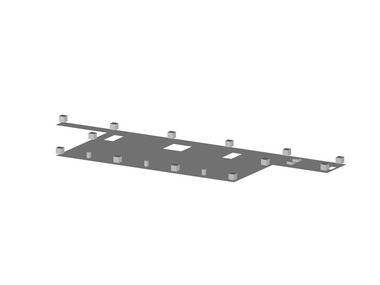
The foundation plate with a length of about 102 ft and a width of about 36 ft was modeled as a surface element. The foundation bases under the steel columns are restrained in the foundation plate.
The loads of the steel structure were assigned as nodal loads to the base heads. In RFEM, the elastic supports represent the bored piles. The RFEM feature "Elastic Support via Column in Z" allowed for the adjustment of the FE mesh at the pile heads.
To generate the moving loads due to rail vehicles, it was necessary to define the position of the axes, the loading, and the direction of the rail vehicles in RF‑MOVE Surfaces. Based on the entered data, the add-on module generated several load cases automatically.
Contact us
Do you have questions or need advice?
Contact our free e-mail, chat, or forum support or find various suggested solutions and useful tips on our FAQ page.
Recommended Events
Eurocode 2 | Concrete structures according to DIN EN 1992-1-1
Online Training 11 May 2021 8:30 AM - 12:30 PM
Videos
KB000610 | Automatically Dimensioning the Foundation Slab Geometry with RF-/FOUNDATION Pro
Length 0:40 min
KB 000674 | Defining Mandrel Diameter for Foundation Reinforcement in RF-/FOUNDATION Pro
Length 0:36 min
KB 000605 | Setting the Concrete Cover in RF-/FOUNDATION Pro According to EN 1992-1-1
Length 0:32 min
KB 000655 | Longitudinal reinforcement to be applied for the shear force design according to EN 1...
Length 0:34 min
Models to Download
Knowledge Base Articles

New
Using Modified Stiffnesses for Dynamic Calculations
In RFEM, it is possible to modify stiffnesses for materials, cross -sections, members, load cases, and load combinations in many places.
Screenshots
Product Features Articles

Material Model Orthotropic Masonry 2D
The material model Orthotropic Masonry 2D is an elastoplastic model that additionally allows softening of the material, which can be different in the local x- and y-direction of a surface. The material model is suitable for (unreinforced) masonry walls with in-plane loads.
Frequently Asked Questions (FAQ)
- How are the signs for the release results of a line release and line hinges interpreted?
- How can I create a curved or arched section?
- Is it possible to manually specify a longitudinal reinforcement for design in RF‑PUNCH Pro?
- Can I simulate the cracked state of a concrete cross -section for a bending beam with the "Isotropic Nonlinear Elastic 1D" material model?
- Why is the deflection of the reinforced concrete floor sometimes greater when selecting a larger basic reinforcement?
- I have a question about message no.47 in the RFEM program. What is the exact meaning of the word integrate? What is the resulting effect?
-
If I do not specify any basic reinforcement in RF-CONCRETE Surfaces, I get the value X as additionally required reinforcement. If I enter this value X as the existing basic reinforcement, I correctly do not get any additional required reinforcement.
However, if I enter a lower value than the determined required total reinforcement as the basic reinforcement, the additionally required reinforcement is increased in such a way that the originally required reinforcement content is exceeded. Why? - Why does the RF-CONCRETE Surfaces add-on module not increase the amount of reinforcement until the SLS designs have a design ratio of 1.0?
- How can I get the member end forces to design the connections?
- How can I perform the design of the tension resistance of a smooth column in a smooth bucket column base, that is, the design against pulling out the column?
Customer Projects
Programs Used for Structural Analysis