


The sunlight is concentrated in a receiver located at the top of the tower using a system consisting of hundreds of mirrors. At the receiver, the absorbed solar energy is converted into thermal energy by heating salt liquid (Molten Salt Liquid - MSL), which is then stored in a container for up to 12 hours. The steam that is heated by the MSL solution in the steam generator drives a turbine that powers the generator.
Structure
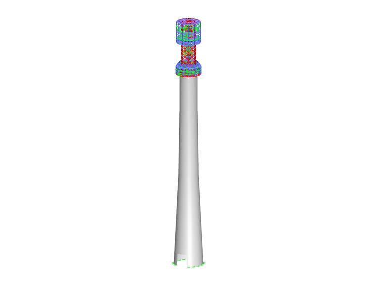
The tower structure consists of a lower reinforced concrete section with a height of 147.5 m (483.9 ft) and a steel structure of the solar receiver with a height of 41 m (134.5 ft). The structural steel design of the receiver was designed in RFEM by the Czech company ALLCONS Industry s.r.o., a customer of Dlubal Software.
Since the solar power plant complex is located in an earthquake-prone area high above sea level, where severe weather conditions prevail, it was very challenging to design the steel structure. Furthermore, all calculations had to be performed according to Chinese standards. When designing the steel structure of the receiver, variable temperature conditions at the receiver had to be taken into account, because the solar panels' surfaces are exposed to heat flux in sunlight that is 1,000 times higher than the normal solar flux. To ensure smooth expansion between the steel and concrete sections of the structure, a special multi-level anchoring system has been developed to allow movement of the structure in the radial direction.
With regard to the height and cylindrical shape of the tower, it was also necessary to take the wind load into account, which may result in transverse vibration due to wind turbulence. Calculations on the effects of wind and seismicity were performed on a complete tower model in RFEM, which is why close cooperation was necessary with the Chinese team that designed the lower concrete section of the tower. Thanks to good mutual cooperation, it was possible to reach agreement in the results of both teams with a maximum deviation of 1%.
| Investor | Luneng Group Co., Ltd. |
| Design of Steel Structure | Allcons Industry s.r.o. |
| General Contractor | Shandong Electric Power Construction Corporation III (SEPCO III) |
| Technology Designer | Cockerill Maintenance & Ingenierie s.a. (CMI) |
![Visualization of Solar Power Plant (© Cockerill Maintenance & Ingenierie sa [CMI])](/en/webimage/012579/568396/Solar_Plant.jpg?mw=720&hash=627228a057bfd9e0a8d7c6d1a81a15fadd8bdba4)

![Visualization of Solar Power Plant (© Cockerill Maintenance & Ingenierie sa [CMI])](/en/webimage/012579/568396/Solar_Plant.jpg?mw=240&hash=9d1e232e918d9f91bce7ef15a02fd693c6333ee3)
