


Completed in 2019, the project is currently the largest cross-laminated timber (CLT) building in the United States. Setting precedence among universities, the U of A is the first to complete a large-scale mass timber residence hall and living learning setting.
Project
The interconnected buildings contain not only the 708 residential units, which are mainly occupied by sophomores, but also catering facilities, classrooms, administrative offices, staff apartments, and much more.
The series of interconnected buildings in serpentine configuration is aimed at providing additional communal outdoor spaces in contrast to traditional campus housing. Additionally, the structure’s advanced timber technologies, with the use of CLT panels and glulam members, was an important sustainability proposal to significantly reduce the building’s carbon footprint.
The project has won numerous awards to date, including:
- AIA St Louis Design Award 2019, Unbuilt Category: Distinguished Award
- Wood Design & Building Honor Award, 2020
- WoodWorks Multi-Family Wood Design Award, 2020
Structure
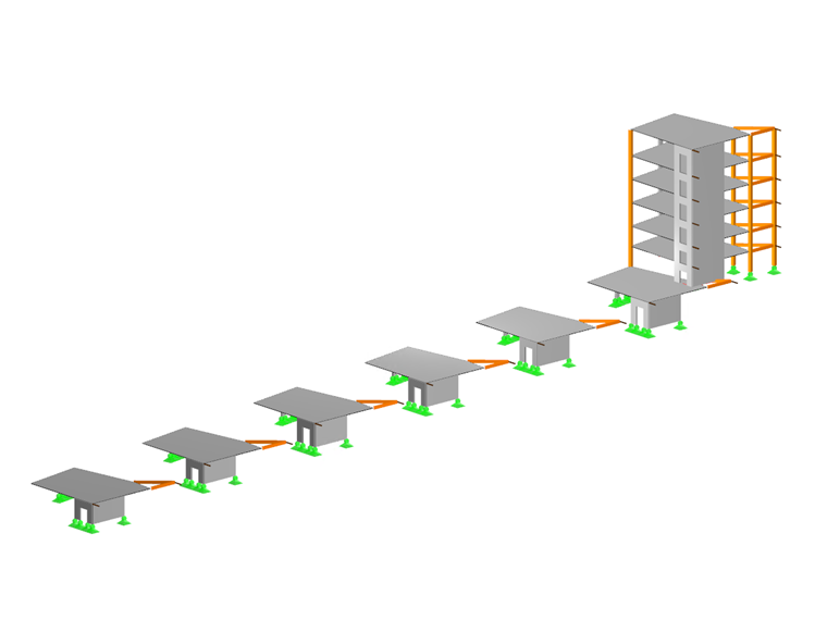
Equilibrium Consulting Inc. engineers used RFEM to model, analyze, and design the building's main components. For the crosswind study, the buildings were considered independently of one another. The individual wings are composed of reinforced concrete cores to which glulam beams and columns are connected.
The design of the cross-laminated timber plates and post-beam structures were carried out in a joint cooperation between Equilibrium Consulting Inc. and the Austrian binderholz group. The glulam beams, columns, and trusses were analyzed individually as simply supported elements. The engineers of Equlibrium utilized RFEM’s add-on modules RF-TIMBER AWC and RF-LAMINATE for the design according to the AWC/NDS standard.
The joist hangers for the glulam beam-column connections were designed using an elastic foundation of the beam. The screws were idealized with linear elastic spring elements.
| Location | 187 S Stadium Dr. Fayetteville, AR 72701 USA |
| Client | University of Arkansas, Fayetteville, AR, USA www.uark.edu |
| Architects | Leers Weinzapfel Associates, Boston, MA, USA www.lwa-architects.com Modus Studio, Fayetteville, AR, USA www.modusstudio.com Mackey Mitchell Architects, St. Louis, MO, USA www.mackeymitchell.com OLIN, Philadelphia, PA, USA www.theolinstudio.com |
| Structural Analysis | EQUILIBRIUM Consulting Inc., Vancouver, BC, Canada www.eqcanada.com |
| Wood Supplier | binderholz group, Fügen, Austria www.binderholz.com |


