


Dlubal customer MARX KRONTAL PARTNER was responsible for the structural analysis and used RSTAB for it.
Structure
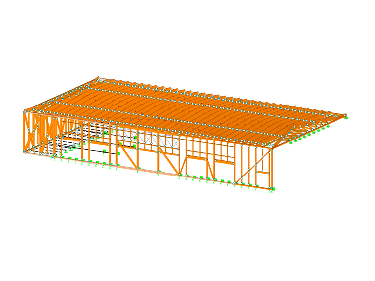
The first floor, made of reinforced concrete, includes four classrooms and locker rooms. Above that, a two-span hall was built as a timber structure. The visible roof structure is an essential design element of the hall interior. The hall is completely acoustically decoupled from the first floor. Elastomer bearing strips under the timber-concrete composite slab form the only support of the hall structure.
The cantilever of the upper floor is made by truss structures integrated into the wall panels. The nodes are a special feature. On one hand, they are designed in such a way that the wall panels can be delivered to the construction site as closed, prefabricated elements, and assembled on site to build a complete structure. On the other hand, the connection details with high load-bearing capacity and low deformation have been developed using inclined, fully threaded screws subjected to tension.
| Location | Alice-Salomon-Schule Kirchröder Str. 13 30625 Hanover Germany |
| Investor | Region Hannover Hildesheimer Road 20 30169 Hannover |
| Architect | [pfitzner moorkens] architekten www.pfitzner-moorkens.de |
| Structural Design | MARX KRONTAL PARTNER www.marxkrontal.com |
![Visualization of Sports Hall (© [pfitzner moorkens] architects)](/en/webimage/033955/4135187/20200311140016_lg2.jpg?mw=720&hash=81ef0a304db3092902f640324e75d7f3f410ecfa)


![Visualization of Sports Hall (© [pfitzner moorkens] architects)](/en/webimage/033955/4135187/20200311140016_lg2.jpg?mw=240&hash=c67e0f8d799a617391954949927feb6efe68bb17)


